4 electrical connection – JUMO 709040 TYA-110 thyristor power unit Operating Manual User Manual
Page 24
4 Electrical connection
24
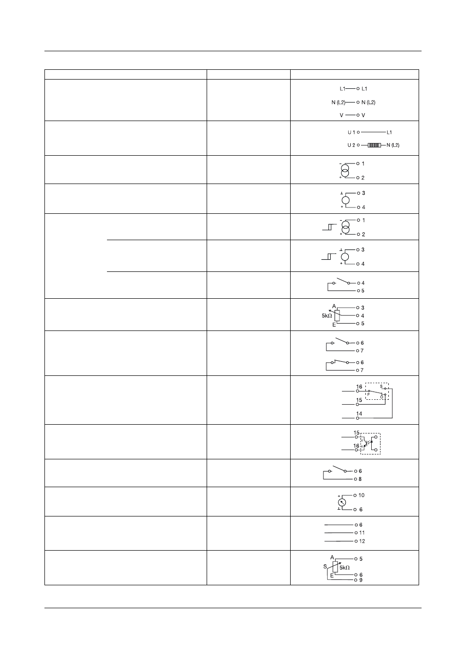
Connection for
Pin assignment
Symbol
Supply voltage for control electronics;
link V to N/L2, unless economy circuit is being used
L1
(line / phase 1)
N/L2 (neutral / phase 2)
V
Load connection
U1
U2
Current input
(differential input)
1-
2+
Voltage input
(referred to ground)
3
⊥
4+
Logic input
Current signal 0/20 mA
1-
2+
Voltage signal 0/10 V
3
⊥
4+
Floating contact
4+
5 (+10V, 2mA)
External manual adjustment with 5 k
Ω potentiometer
(via voltage input)
3 Start (
⊥)
4 Slider
5 End (+10V, 2mA)
Firing-pulse inhibit input I
K
≈ 1mA
(make or break contact)
6
⊥
7+
Load-failure output with relay,
switching capacity 5A at 230 V AC, resistive load.
Relay drops out if fault occurs.
(extra code TR)
16 P pole
15 O break contact
14 S make contact
Load failure output with optocoupler
I
Cmax.
= 2mA U
CEO max.
= 32V
(extra code TO)
15 Collector
16 Emitter
External changeover of operating mode
(phase-angle or burst-firing operation)
6
⊥
8+
Actual (power) output 0 — 10V
I
max
≈ 2mA
10+
6
⊥
Master-slave connection for
master-slave economy circuit
6
⊥
11
12
External current limiting
with 5 k
Ω potentiometer
5 Start (+10V, 2mA)
6 End (
⊥)
9 Slider
or
- 7050xx mTRON T - System description (10 pages)
- 705040 mTRON T - Router Module Operating Manual (74 pages)
- 705040 mTRON T - Router Module Installation Instructions (34 pages)
- 705030 mTRON T - Digital Input/Output Module Data Sheet (7 pages)
- 705030 mTRON T - Digital Input/Output Module Operating Manual (50 pages)
- 705021 mTRON T - Analog Input Module, 8-Ch. Data Sheet (8 pages)
- 705021 mTRON T - Analog Input Module, 8-Ch. Operating Manual (56 pages)
- 705020 mTRON T - Analog Input Module, 4-Ch. Data Sheet (10 pages)
- 705020 mTRON T - Analog Input Module, 4-Ch. Operating Manual (70 pages)
- 705015 mTRON T - Relay Module 4-Ch. Data Sheet (5 pages)
- 705015 mTRON T - Relay Module 4-Ch. Operating Manual (44 pages)
- 705010 mTRON T - Multichannel Controller Module Data Sheet (15 pages)
- 705010 mTRON T - Multichannel Controller Module Operating Manual (148 pages)
- 705001 mTRON T - Central Processing Unit Data Sheet (10 pages)
- 705001 mTRON T - Central Processing Unit Operating Manual (152 pages)
- 705060 mTRON T - Multifunction Panel 840 Data Sheet (13 pages)
- 705060 mTRON T - Multifunction Panel 840 Operating Manual (272 pages)
- 709062 TYA 202 - Three-Phase Power Controller Data Sheet (17 pages)
- 709062 TYA 202 - Three-Phase Power Controller Operating Manual (112 pages)
- 709061 TYA 201 - Single-Phase Power Controller Data Sheet (21 pages)
- 709061 TYA 201 - Single-Phase Power Controller Operating Manual (112 pages)
- 709050 IPC IGBT Power Converter Data Sheet (12 pages)
- 709050 IPC IGBT Power Converter IPC 200A Operating Manual (52 pages)
- 709050 IPC IGBT Power Converter IPC 70/100A Operating Manual (52 pages)
- 709050 IPC IGBT Power Converter IPC 70A Operating Manual (48 pages)
- 709040 TYA-110 thyristor power unit Data Sheet (12 pages)
- 709020 TYA-432 thyristor power switch Data Sheet (5 pages)
- 709010 TYA-432 thyristor power switch Data Sheet (3 pages)
- 706585 LOGOSCREEN fd Data Sheet (21 pages)
- 706585 LOGOSCREEN fd Operating Instructions (108 pages)
- 706585 LOGOSCREEN fd Operating Manual (228 pages)
- 706585 LOGOSCREEN fd Recorder with diecast zinc front Installation Instructions (40 pages)
- 706585 LOGOSCREEN fd Recorder with stainless steel front Installation Instructions (52 pages)
- 706581 LOGOSCREEN nt Data Sheet (18 pages)
- 706581 LOGOSCREEN nt Operating Instructions (108 pages)
- 706581 LOGOSCREEN nt Operating Manual (224 pages)
- 706581 LOGOSCREEN nt Paperless Recorder with TFT display, CompactFlash Installation Instructions (36 pages)
- 706581 LOGOSCREEN nt stainless steel front Installation Instructions (48 pages)
- 706560 LOGOSCREEN es Data Sheet (12 pages)
- 706560 LOGOSCREEN es Operating Instructions (64 pages)
- 706560 LOGOSCREEN es Operating Manual (128 pages)
- 706560 LOGOSCREEN es Installation Instructions (32 pages)
- 706510 LOGOSCREEN 500 cf Data Sheet (10 pages)
- 706510 LOGOSCREEN 500 cf Operating Manual (140 pages)