3 adjusting the crystal holder retainer spring – INFICON UHV Bakeable Sensor User Manual
Page 41
4 - 7
PN
07
4-
15
4N
UHV Bakeable Sensor Operating Manual
4.3.3 Adjusting the Crystal Holder Retainer Spring
Occasionally, the ceramic retainer may not be secured in the crystal holder. To alter
the retainer retention force, use the following procedure.
Tools required
Scribe or other pointed tool
Needle nose pliers (two required)
Procedure
1
Position the crystal holder with the crystal aperture oriented downward.
2
Insert the point of the scribe between the inside edge of the crystal holder cavity
and one of the two wire segments that protrude into the crystal cavity (see
(a)).
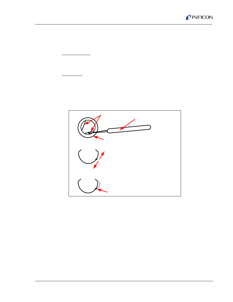
Figure 4-5 Location of the transition point
3
Using the scribe, gently remove the spring from its groove in the
crystal holder cavity.
4
Refer to
(b) to determine the direction in which the ‘transition point’
must be relocated, to attain the desired retention forces. Moving this transition
point approximately 1.59 mm (1/16 in.) is generally sufficient.
5
Grasp the spring, with the pliers, just below the transition point. Use the second
set of pliers to bend the spring as illustrated by the dashed line in
(c)
to remove the existing transition point.
6
Use both pliers to form a new transition point according to
(b),
thus returning the spring to a shape similar to the solid line delineation
of
(c).
Wire
Scribe
Crystal Holder
Move location of transition point in this
direction to decrease retainer retention force
Move location of transition point in this
direction to increase retainer retention force
Location of Transition Point
(a)
(b)
(c)