Section 1.4.1 – INFICON UHV Bakeable Sensor User Manual
Page 12
1 - 4
PN
07
4-
15
4N
UHV Bakeable Sensor Operating Manual
1.4.1 UHV Bakeable Sensor Configuration Overview and Parts
UHV Bakeable Sensor . . . . . . . . . . . . . . BK-AXF (see
)
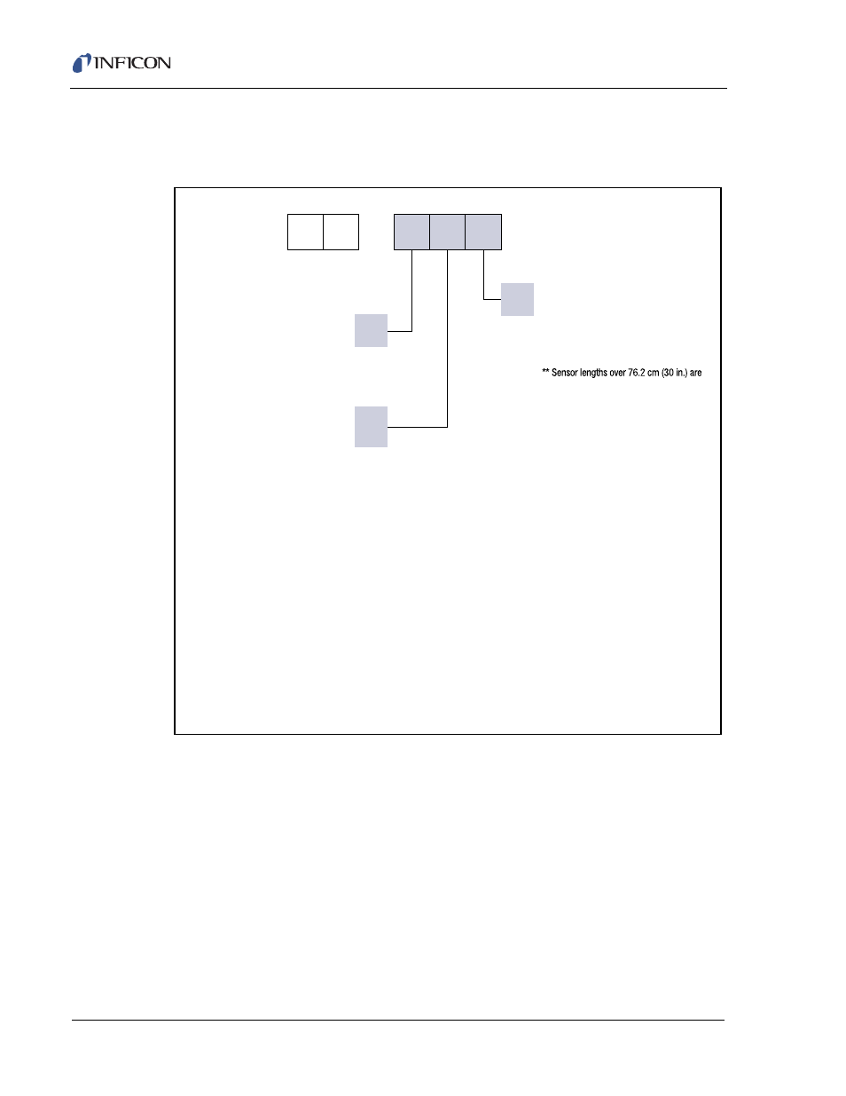
Figure 1-2 UHV Bakeable Sensor configurations
Thin Film Manuals CD . . . . . . . . . . . . . . . . . . . . . . . PN 074-5000-G1
Crystal Snatcher. . . . . . . . . . . . . . . . . . . . . . . . . . . . PN 008-007
Molybdenum Disulfide in Isopropyl Alcohol . . . . . . . PN 750-191-G1
Graphite in Isopropyl Alcohol
(provided only with shuttered sensors) . . . . . . . . . . PN 009-175
F
0
1
B K –
A
NOTE 1:
Orders cannot be entered without a completed sensor length
specification form (provided by INFICON). Once order is confirmed,
it cannot be canceled.
NOTE 2:
Sensor lengths are measured from the center of the crystal to
the vacuum side (sealing surface) of the feedthrough (see length
specification form).
NOTE 3:
All UHV Bakeable Sensors are welded to a CF40 feedthrough.
NOTE 4:
Shutter air tube is connected to the feedthrough tube using a
VCR® fitting.
Type of Sensor
(crystals sold separately)
Standard
(water lines parallel to crystal face)
Shutter Assembly
None
Standard shutter
Length of Sensor
Standard length –
Shuttered sensors
From 17 to 101.6 cm (6.7 to 40 in.)
Non-shuttered sensors
From 10.2 to 101.6 cm (4 to 40 in.)
subject to an additional charge, as well
as 2-4 weeks additional lead time.