User made accessories - stop, User made accessories - right angle fixture, Making a stop positioner – INCRA Jig User Manual
Page 4: Fig. 12, Fig. 11, Fig. 10, Making a right angle fixture, Fig. 13 fig. 13b, Fig. 13c, Fig. 14
4
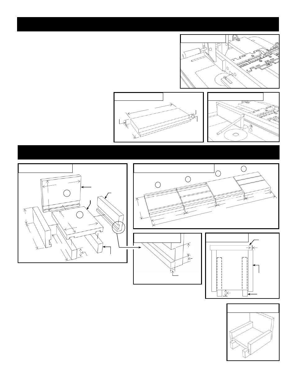
User Made Accessories - Stop
Making a Stop Positioner
Your stop positioner is useful for limiting the length of cuts made at the
router table. Just position the stop and secure it to the fence with a
wooden hand screw clamp, Fig 10. This is perfect for the stopped
cuts required for the dovetail pin cuts described in the joinery section of
this manual.
The simple design shown in Fig. 11 includes a rabbeted area that
allows moving the stop over the top of the cutter for very short stopped
cuts. 3/4” MDF will make a good stop material.
TIP: When making fine adjustments
relative to an initial stop position, place a
mark on the front face of the fence along
the leading edge of the stop positioner,
Fig. 12. Now when you loosen the clamp
and slide the stop you can easily gauge
how much you have moved the positioner.
3/4”
1/2”
1/2”
8”
3”
Fig. 12
Marking stop position
Fig. 11
Stop dimensions
Fig. 10
Stop positioner
Making a Right Angle Fixture
This simple Right Angle Fixture is an important
accessory for joinery. Use it to guide your material
for the vertical cuts required for dovetails and box
joints as shown beginning on page 7.
To make the design shown in Figs. 13 & 14, begin with (4) identical pieces of 3/4”
MDF, cut to 5 1/2” x 6 1/2”. Cut (2) pieces “A”, (1) piece “B” and (1) piece “C” as shown in
Fig 13A. To cut ALL the grooves as shown in Fig. 13B, set a 3/4” diameter router bit to 1/4”
depth of cut, and set the fence-to-bit distance at 3/8”. Check the fit of the material in the
grooves, then fine tune as necessary. Now, rip (1) piece “A” to yield (2) 2 5/8” wide Side
pieces. Then rip the final uncut blank “C” to yield the (2) 1 3/8” Runners.
To assemble, first glue the (2) Runners to the Base, allowing 3/4” of overhang as shown in
Fig. 13C. Now glue the Faceplate and the (2) Sides to the Base. Make sure that the
Faceplate is offset 1/8” from the fence Side piece as shown in Fig. 13C, and that the
Faceplate and the fence Side piece are square to your table top.
User Made Accessories - Right Angle Fixture
5 1/2”
6 1/2”
2 5/8”
6 1/2”
6 1/2”
1 3/8”
6 1/2”
5 1/2”
Fig. 13
Fig. 13B
Groove detail
3/4”
3/8”
1/4”
Material:
3/4” MDF
3/4”
1/8”
Runner (2)
This Side bears
against fence
Fig. 13C
Top view
A
B
Runner (2)
Faceplate
Side (2)
Fig. 14
Finished Fixture
A
B
Faceplat
e
Runner
Side
Runner
Side
A
Base
Waste
C
6 1/2”
26 3/8
”
6 1/2”
6 1/2”
6 1/2”
Fig. 13A
Right Angle Fixture cutting diagram
5 1/2”
Right Angle Fixture
Base
Base
Faceplate
All grooves are 3/4”
wide by 1/4” deep
and located 3/8”
from the material
edge