Festo DSL-16 … 40-270-…-B User Manual
Page 4
9.Press the protective cap of the DSL back onto the snap
ring of the housing (if present).
The protective cap can also be snapped onto freely
positioned shock absorber retainers if the elements
are broken through at the predetermined breaking
point. Observe the fitting instructions for the cover cap.
When all stops have been adjusted:
• Check whether additional shock absorbers or stops are
necessary.
Additional shock absorbers or stops are necessary in
the following cases:
– for movable masses with a calculated mass moment
of inertia greater than the
permitted mass moment of
inertia
– when the DSL is operated without an air cushion on
the exhaust side (e.g. after long breaks between
the individual swivel movements).
Shock absorber retainers for internal fitting of shock
absorbers/elastomer absorbers can be ordered
separately and installed on the DSL (
Accessories).
4.3 Fitting pneumatic components
• Use GRLA one-way flow control valves for setting the
swivel speed and stroke speed.
These are screwed directly into the compressed air
ports.
With eccentric masses:
• Check whether HGL controlled non-return valves or a
VZS compressed air reservoir are necessary.
In this way you can prevent the moveable mass from
sliding down suddenly if there is a sudden drop in pres-
sure.
4.4 Fitting electric components
For sensing the cylinder end positions:
• Place the proximity switches
aF in the double groove of
the profile.
1.Lift up the cover cap
2 with a flat screwdriver.
2.Push a proximity switch
aF for each of the end posi-
tions into a groove.
3.Press the cover cap tight again.
aF
2
For sensing the swivel end positions:
• Place the proximity switches on the guide rim
aG of the
absorber retainers.
Sensor supports (
Accessories) are required for
fastening the proximity switches.
The proximity switch is actuated by the magnet
aH in
the stop lever.
aG
aH
5 Commissioning
5.1 Commissioning the complete system
• Pressurise your entire system slowly.
This will prevent uncontrolled movements from
occurring.
5.2 Commissioning an individual unit
Warning
. . . . . . . . . . . . . . . . . . . . . . . . . . . . . . . . . . . . . . . . . . . . . . . . . .
Risk of injury from rotating masses.
• Make sure that the DSL is set into motion only when
the safeguards are fitted.
• Make sure that:
– nobody can reach into the swivel/positioning
range of the DSL
– no objects lie in the positioning path (e.g. by
providing an individual protective screen).
1.Tighten the two upstream one-way flow control valves
– first close completely
– then loosen approximately one turn.
2.Make sure that the operating conditions lie within the
permitted ranges.
3.Pressurise the drive in one of the following ways:
–
slow pressurisation of one side of the swivel or linear
component
– simultaneous pressurisation of both sides with
subsequent exhausting of one side.
4.Start a test run.
5.During the test run check whether the following
settings on the DSL need to be modified:
– the swivel range of the moveable mass
– the swivel speed of the moveable mass.
6.Unscrew the one-way flow control valves slowly until
the desired swivel speed is set. The stop lever
6
should reach the end position, but not strike hard
against it.
Note
. . . . . . . . . . . . . . . . . . . . . . . . . . . . . . . . . . . . . . . . . . . . . . . . . . . . . .
If the impact is too hard, it will cause the stop lever to
rebound out of the end position, resulting in a reduc-
tion of the service life.
If the stop lever can be heard to strike hard:
7.Interrupt the test run.
Causes of hard knocking may be:
– Mass moment of inertia of the moveable mass too
high.
– Swivel speed of the moveable mass too high.
– No compressed air cushion on the exhaust side.
– Insufficient shock absorption.
8.Make sure you remedy the above-mentioned causes.
9.Repeat the test run.
When all necessary corrections have been undertaken:
10. Conclude the test run.
5.3 Fine adjustment of the end positions
Note
. . . . . . . . . . . . . . . . . . . . . . . . . . . . . . . . . . . . . . . . . . . . . . . . . . . . . .
A shock absorber that is screwed too far in or out
results in the stop lever:
– either hitting the shock absorber retainer without
shock absorption
or
– hitting the shock absorber at an impermissible angle.
In such a case there is a risk of the DSL or the shock
absorber being damaged.
• Make sure that you do not screw the shock absorber
in or out any further than shown in the following ta-
ble.
Otherwise the shock-absorbing performance of the
shock absorber/elastomer absorber will be insuffi-
cient or even completely ineffective.
• Pressurise the desired end position on the DSL.
The end positions can be adjusted under pressure.
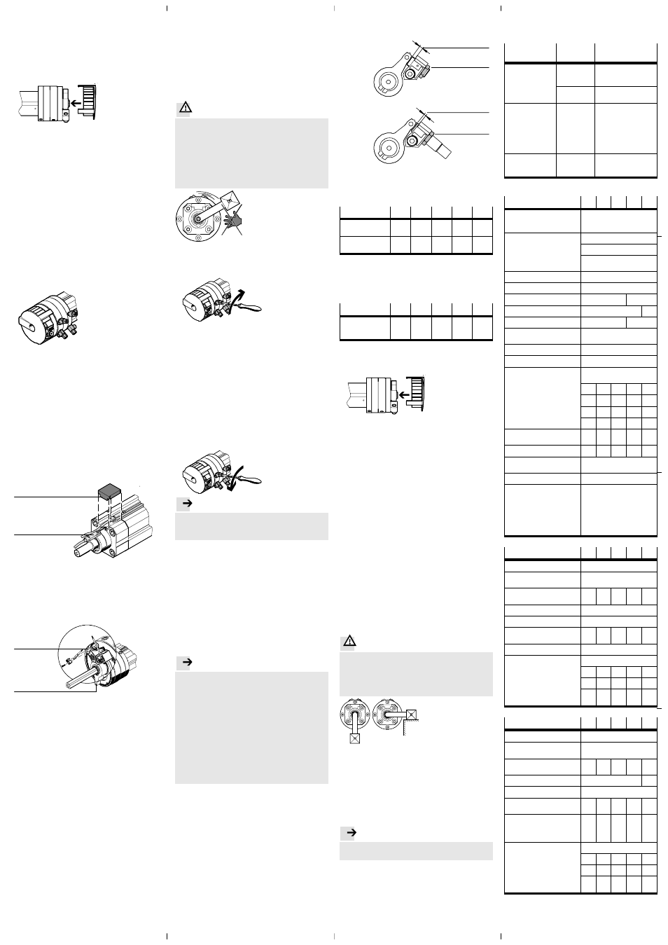
1.Remove the protective cap from the housing
(if present).
2.Unscrew the locking nut
bJ of the shock absorber.
The unscrewing length of the shock absorber (Elas-
tomer absorber
aI or shock absorber bA) can be used
to compensate the deviation of the end position.
This occurs during pre-adjustment when the shock ab-
sorber is moved against the unpressurised stop lever.
bJ
aI
DSL-...-P
DSL-...-CC
bA
bJ
3.Screw the shock absorber into or out of the shock ab-
sorber retainer using a hexagon spanner.
The permissible unscrewing lengths are summarised in
the following table.
DSL-…-270-...-B
16
20
25
32
40
Unscrewing
length
aI
[mm] 0 … 2.5
0 … 3
0 … 4
0 … 4.5
0 … 5.4
Screwing-in
length
bA
[mm] 0 … 1.25 0 … 1.5
0 … 2
0 … 2.25 0 … 2.7
When all stops have been adjusted:
4.Tighten the locking nuts
bJ of the shock absorbers
again.
The necessary tightening torques are summarized in
the following table.
DSL-…-270-...-B
16
20
25
32
40
Tightening
torque of the
locking nut
bJ
[Nm] 2
3
3
5
20
5.Check that the proximity switches function correctly.
6.Press the protective cap of the DSL back onto the snap
ring (if present).
7.Repeat the test run.
6 Operation
With several uninterrupted swivel cycles:
• Make sure that the maximum permitted swivel
frequency is not exceeded (
Technical specifications).
Otherwise, functional reliability will be impaired by
excessive heating.
To extend the service life of the shock absorbers:
• Apply a thin coating of grease to the stop caps of the
shock absorbers.
Checking for proper functioning:
• Check the shock absorbers for oil loss after every 2 mil-
lion switching cycles.
• Change shock absorbers with visible oil loss or at the
latest every 5 million switching cycles (
Accessories).
7 Care and maintenance
If the device is dirty:
• Clean the DSL with a soft cloth.
All non-abrasive cleaning agents are permitted
(e.g. warm soap suds up to +60 °C).
8 Dismantling and repairs
With eccentric masses on the lever arm:
Warning
. . . . . . . . . . . . . . . . . . . . . . . . . . . . . . . . . . . . . . . . . . . . . . . . . .
Risk of injury from masses that slide down suddenly if
there is a drop in pressure.
• Make sure that the mass has reached a stable posi-
tion before the DSL is exhausted (e.g. the lowest
point).
Recommendation:
• Return the product to our Repair Service.
The necessary accurate adjustments and tests will then
be taken into account.
• Information on spare parts and aids can be found
under: www.festo.com/spareparts.
9 Accessories
Note
. . . . . . . . . . . . . . . . . . . . . . . . . . . . . . . . . . . . . . . . . . . . . . . . . . . . . .
• Please select the appropriate accessories from our
catalogue www.festo.com/catalogue.
10 Eliminating faults
Fault
Possible
cause
Remedy
Uneven movement of
the moveable mass
Flow control
valves inserted
incorrectly
Check the flow control
valve function (exhaust air
flow control)
Asymmetric
angle setting
Symmetric setting
preferred
– Hard impact at the
end position
– Piston rod does
not remain in the
end position
Residual energy
too high
– Select smaller stroke or
swivel speed
– Use external shock
absorbers
– Move only against
residual air cushion
on the exhaust side
– Select a lighter mass
Piston rod moves only
with great difficulty or
not at all
Bending stress
via the drive
rod
Avoid bending stress
(especially on the
square
aB)
11 Technical specifications
DSL-…-270-...-B
16
20
25
32
40
Constructional design
Combined stroke/rotary cylinder
with swivel vane – in each case
double-acting
End position cushioning
– Linear motion
P – not adjustable at either end
– Swivel component
None (may only be operated with
shock absorption)
Mounting position
as desired
Min. stroke length
[mm] 10
Max. stroke length
DSL
[mm] 160
200
Max. stroke length
DSL-KF
[mm] 100
160
Pneumatic connection
M5
G
Á
Operating medium
Filtered compressed air,
lubricated or unlubricated
Operating pressure
[bar]
2.5 … 8
Ambient temperature
[°C]
–10 … +60
Theoretical effective
power F
X
at 6 bar
– advancing
DSL
[N]
102.5 159
246
422.5 660
– retracting
DSL
[N]
73.5
120.5 173.5 294
495
– advancing
DSL-KF
[N]
103.5 158
248
403.5 603
– retracting
DSL-KF
[N]
73.5
120.5 173.5 294
495
Permitted dynamic
load torque
DSL-KF
[Nm]
0.17
0.35
0.7
1.0
5.4
Torque at 6 bar
[Nm]
1.25
2.5
5
10
20
Max. piston speed of
linear component
[mm/s] 500
Note on materials
free of copper and PTFE
Materials:
– housing, flange stop lever,
cover
– piston rod / shaft
– swivel vane, cap
– stop screw,
stops, screws
– seals
anodised aluminium
steel, nickel-plated
fibreglass-reinforced plastic
stainless steel
galvanised steel
polyurethane
DSL-…-270-P-...-B
16
20
25
32
40
End position cushioning
Elastomer shock absorbers
End position adjustment
via elastomer shock absorbers
with fixed stop
Max. permissible mass
moment of inertia
[10
-4
kg m
2
]
0.35
0.7
1.1
1.7
2.4
Swivel angle
[°]
270
Swivel angle adjustment
[°]
-6
Shock absorbing angle,
single
[°]
1.8
1.4
1.2
1.4
2
Swivel frequency
[Hz]
2
Weight
[kg]
– Basic weight
DSL
0.70
1.09
1.61
2.99
5.30
– Basic weight
DSL-KF
0.75
1.18
1.66
3.02
5.21
– Linear component per 10 mm
stroke
0.033 0.052 0.067 0.109 0.175
DSL-…-270-CC-...-B
16
20
25
32
40
End position cushioning
Shock absorbers
End position adjustment
via shock absorbers with fixed
stop
Max. permissible mass
moment of inertia
[10
-4
kg m
2
]
7
12
16
21
40
Swivel angle
[°]
246
240
Swivel angle adjustment
[°]
-3
Shock absorbing angle,
single
[°]
15
12
10
12
16
Swivel frequency with
2 shock absorbers
– at max. swivel angle
– at smaller swivel angles
1.5
2
1
1.5
1
1.5
0.7
1.5
0.7
1.5
Weight
[kg]
– Basic weight
DSL
0.7
1.13
1.61
3.02
5.21
– Basic weight
DSL-KF
0.75
1.22
1.75
3.30
5.36
– Linear component per 10 mm
stroke
0.033 0.052 0.067 0.109 0.175