Festo DSL-16 … 40-270-…-B User Manual
Page 3
Note
. . . . . . . . . . . . . . . . . . . . . . . . . . . . . . . . . . . . . . . . . . . . . . . . . . . . . .
en Fitting and commissioning to be carried out only
by qualified personnel in accordance with the
operating instructions.
Note the warnings and instructions on the product
and in the relevant operating instructions.
The specifications/instructions in the relevant
documentation supplied with the product must be
observed.
First read through all the operating instructions
supplied with the product. In this way you can
avoid extra expense due to any necessary correc-
tive measures.
1
3
4
6 7
8
9
aE
aA aJ
aB
5
aC
2
aD
1
Thread for fastening
2
Cover cap
3
Double groove for proximity switch
4
Compressed air connections for linear
component
5
Compressed air supply ports for swivel
component
6
Angle scale
7
Snap ring for protective cap
8
Shock absorber with locking nut (optional)
9
Shock absorber retainer (optional)
aJ
Locking screw for absorber retainer
aA
Stop lever with integrated magnet for
position monitoring
aB
Square (projecting length depending on
position of linear component)
aC
Sensor support with proximity switch
(optional)
aD
Groove for fastening with slot nuts
aE
Extendable piston rod with thread and
feather key
Fig. 1
Swivel/linear unit
en
. . . . . . . . . . . . . . . . . . . . . . . . . . . . . . . . . . . . . . . . . . . . .
Type DSL-16 … 40-270-…-B
1 Function and application
The combination of swivel component and linear compo-
nent in one product permits overlapping movements.
When the compressed air ports are pressurised alter-
nately, the inner vane in the housing swivels backwards
and forwards. This swivel movement is transmitted to
the outer stop lever and converted to a rotary movement
on the piston rod. The angle of rotation can be limited
for the stop lever by means of adjustable shock ab-
sorber elements (elastomer absorbers or shock ab-
sorbers).
Irrespective of this, the piston rod extends or retracts
when the relevant compressed air ports are pressurised
alternately.
The DSL swivel-linear module has been designed for the
combined movement of work loads which do not have to
carry out a complete revolution.
2 Transport and storage
• Take into account the weight of the DSL:
It weighs up to 7 kg.
• Ensure storage conditions as follows:
– Storage times should be kept to a minimum
– cool, dry, shaded storage locations protected from
corrosion.
3 Conditions of use
Note
. . . . . . . . . . . . . . . . . . . . . . . . . . . . . . . . . . . . . . . . . . . . . . . . . . . . . .
Malfunctions will occur if the device is not used
correctly.
• Ensure that the specifications in this chapter are
always observed.
• Note the warnings and instructions on the product
and in the relevant operating instructions.
• Compare the maximum values specified in these
operating instructions with your actual application
(e.g. pressures, forces, torques, temperatures,
masses).
The product can only be operated in accordance with
the relevant safety guidelines if the maximum loading
limits are observed.
• Take into consideration the ambient conditions at the
location of use.
Corrosive elements in the environment (e.g. ozone) will
reduce the service life of the product.
• Ensure that all applicable safety regulations are ob-
served, e.g. from trade associations or national auth-
orities.
• Remove the packaging.
It is intended that the packaging be recycled on the
basis of its constituent materials (exception: oiled
paper = other waste).
• Ensure that the compressed air is properly prepared
(
Technical specifications).
• Use the same medium composition throughout the
service life of the product. Example:
If unlubricated compressed air is selected at the outset,
then unlubricated compressed air should be used dur-
ing the complete service life of the product.
• Pressurise your complete system slowly until the oper-
ating pressure is reached. This ensures that all actuator
movement is controlled.
For slow start-up pressurisation use safety start-up
valve type HEL.
• Use the product in its original state. Unauthorised
modification is not permitted.
4 Fitting
4.1 Fitting mechanical components
Definition
moving mass = work load (+ mass of any levers)
• Handle the DSL with care so that the piston rod or
square is not damaged. This applies in particular to the
following points:
• Position the DSL so that you can easily reach the oper-
ating parts.
• Fasten the DSL as follows:
– with at least 2 screws and slot nuts in the groove
aD
on the linear component of the DSL
– on the central nut (M) on the DSL-16
– over a flange (F) on the centring collar on the drive
take-off side of the DSL-20 ... 40.
aD
(M)
(F)
Using the square
aB for optional purposes:
• Avoid lateral forces on the square
aB.
Additional optional purposes are e.g.:
– axial, touching scanning
– axial cushioning.
A light additional element (e.g. a stop or switching cam)
can be mounted on the square.
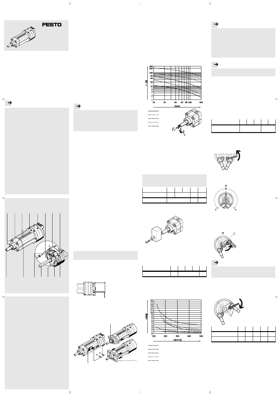
• When placing the moveable mass, make sure that the
following points are observed:
– the device must not be tilted,
– permissible radial force Fz (diagram below),
– effective power Fx (
Technical data),
– permissible mass moment of inertia (
Technical
specifications).
DSL-16
DSL-20
DSL-25
DSL-32
DSL-40
z
The mass moment of inertia of the moveable mass
should be calculated. Lever arms, jibs and masses,
as well as masses on the square must be taken into
consideration in the calculation.
The permissible mass moment of inertia (
Catalogue
specifications) depends on the specific situation:
– the size of the DSL
– the type of end-position cushioning
– the swivel time
– the swivel angle
– the stroke time
Definition
Swivel time = rotation time of the inner vane +
cushioning time from the shock absorber
DYSC
DSL-…-270-...-B
16
20
25
32
40
DYSC-…
5-5
7-5
8-8
12-12
Cushioning time
[s] 0.1
0.25
0.3
Fastening the work load
• Push the moveable mass onto the piston rod:
• Make sure that the moveable mass cannot slide down
from the piston rod.
The thread in the piston rod serves this purpose.
When tightening the screws, counter-lock at the work
load.
• Note the following tightening torque:
DSL-…-270-...-B
16
20
25
32
40
Tightening torque
[Nm]
1.2
5.5
10
• Note the following correlation of permitted work load
and piston speed v:
Eccentric masses on the horizontal lever arm increase
the inner friction. The effective power of the linear
movement is thereby reduced (not with DSL-...-KF).
DSL-16
DSL-20
DSL-25
DSL-32
DSL-40
4.2 Adjusting the DSL with an internal stop system
Using
external stops and shock absorbers
Note
. . . . . . . . . . . . . . . . . . . . . . . . . . . . . . . . . . . . . . . . . . . . . . . . . . . . . .
• Make sure that the following points are observed:
– The target point in the mass moment of inertia
(important with eccentric masses on the lever
arm)
– The permitted radial force Fz (
Chapter “Fitting
mechanical components”)
– Using protective devices
(e.g. cover cap
Accessories)
Note
. . . . . . . . . . . . . . . . . . . . . . . . . . . . . . . . . . . . . . . . . . . . . . . . . . . . . .
Operation without shock absorbers will destroy
the DSL.
1.Remove the protective cap of the DSL from the housing
(if present).
2.Screw the shock absorber elements (elastomer ab-
sorbers or shock absorbers) into the shock absorber
retainer.
The accompanying documentation must be observed.
3.Swivel the moveable mass to the desired end position:
– by hand
– with open-end wrench on the square
aB.
(not with DSL-...-KF)
The angle scale on the housing ring serves as a first
orientation.
DSL-…-270-...-B
16
20
25
32
40
Degree setting (1
graduation =)
[°]
2
1
4.Unscrew the locking screws for the shock absorber
retainers. To shift the shock absorber retainers it is
sufficient to slacken the locking screws until they can
just barely be shifted.
5.If possible use symmetric angle settings that follow line
of symmetry M of the DSL. These produce a more even
movement between right-hand and left-hand rotation.
6.Push the nearby shock absorber retainer towards the
stop lever against the force of the shock absorber until
the fixed stop of the shock absorber (elastomer ab-
sorber or shock absorber) touches the stop lever.
If necessary, counter-lock on the work load.
Note
. . . . . . . . . . . . . . . . . . . . . . . . . . . . . . . . . . . . . . . . . . . . . . . . . . . . . .
Shock absorber retainers that are fastened with an
insufficient tightening torque may shift under opera-
ting conditions, resulting in damage to the DSL.
7.Tighten the locking screw of the shock absorber
retainer again with the following tightening torque.
Only with the specified tightening torque will the
toothing of the shock absorber retainer bite into the
housing material.
DSL-…-270-...-B
16
20
25
32
40
Locking screw
M3
M4
M5
M6
M8
Tightening torque
[Nm]
2.1
4.9
10
16.5
40
8.Repeat the adjustment for the other end position.
DSL-16 … 40-270-…-B
Operating instructions
Original: German text
Festo AG & Co. KG
Postfach
D-73726 Esslingen,
Germany
Phone:
+49/711/347-0
www.festo.com
0808a
740 210