Connector j2 – ElmoMC Gold Line Digital Servo Drives-Gold Bell User Manual
Page 28
Gold Bell Installation Guide
Installation
MAN-G-BELIG (Ver. 1.004)
28
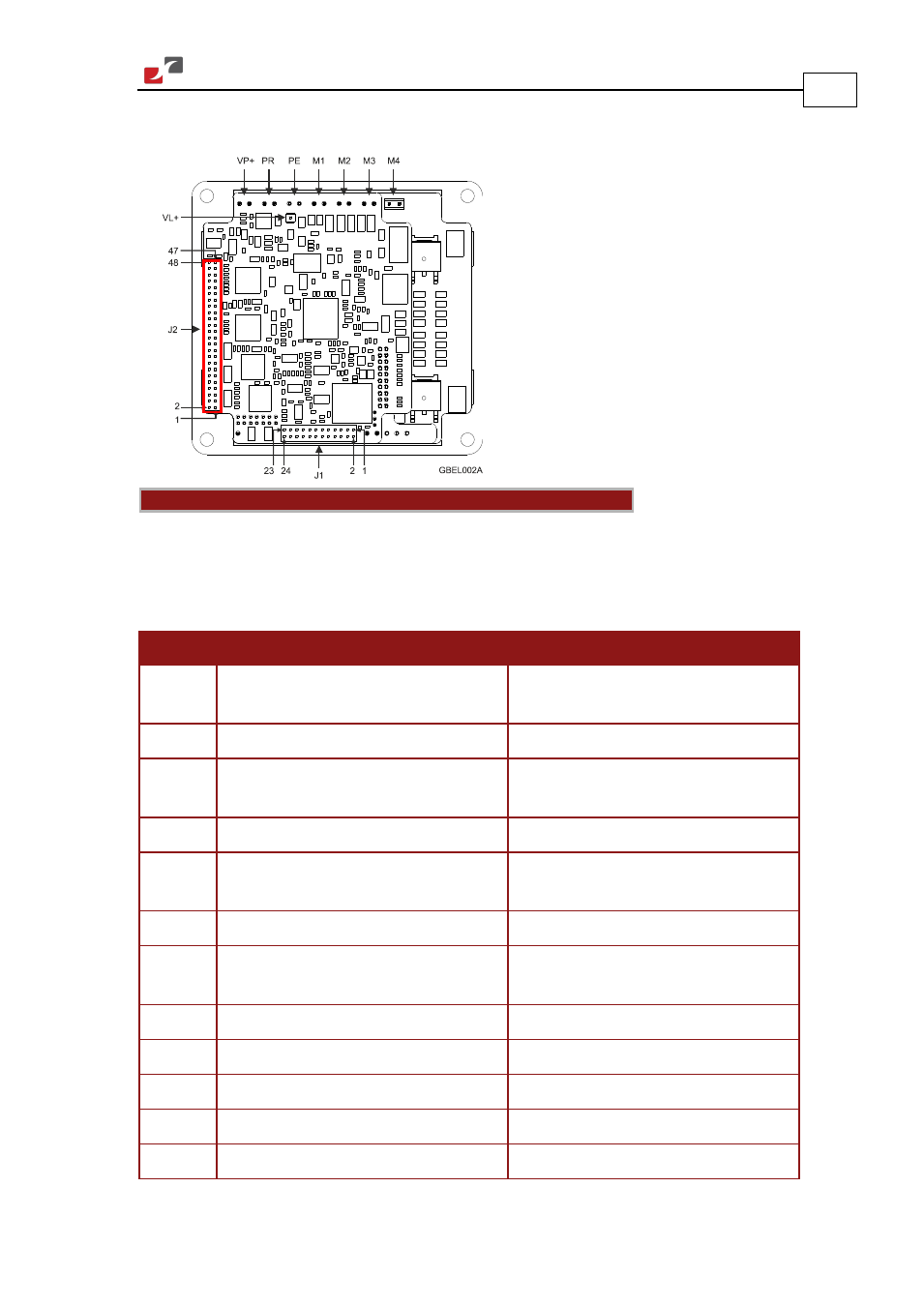
4.3.2.4.
Connector J2
Feedback A/B/C, Digital Halls – see
Section
Analog Inputs – see Section
RS-232, EtherCAT, USB – see Section
Connector Type: 1.27 mm pitch 0.41 mm
sq
Note regarding the EtherCAT and CAN communication options:
The J2 Connector exports all supported communication links. However, note that CAN and
EtherCAT are not available in the same version of the Gold Bell and are thus not operational
simultaneously. See the part number diagram in Section
4.2 above for the different Gold Bell
configurations.
Pin (J2) Signal
Function
1
PortA_ENC_A+ /ABS_CLK+
Port A- channel A/ Absolute encoder
clock+
2
PortC_ENCO_A-
Port C- channel A complement output
3
PortA_ENC_A-/ABS_CLK-
Port A- channel A complement /
Absolute encoder clock-
4
PortC_ENCO_A+
Port C- channel A output
5
PortA_ENC_B+/ABS_DATA+
Port A - channel B/ Absolute encoder
Data+
6
PortC_ENCO_B-
Port C - channel B complement output
7
PortA_ENC_B-/ABS_DATA-
Port A - channel B complement /
Absolute encoder Data-
8
PortCENCO_B+
Port C - channel B output
9
PortA_ENC_INDEX+
Port A – index
10
PortC_ENCO_INDEX-
Port C - index complement output
11
PortA_ENC_INDEX-
Port A - index complement
12
PortC_ENCO_INDEX+
Port C - index output