Det-Tronics R8471J Single Channel Gas Controller, OPECL User Manual
Page 5
1.1
95-8572
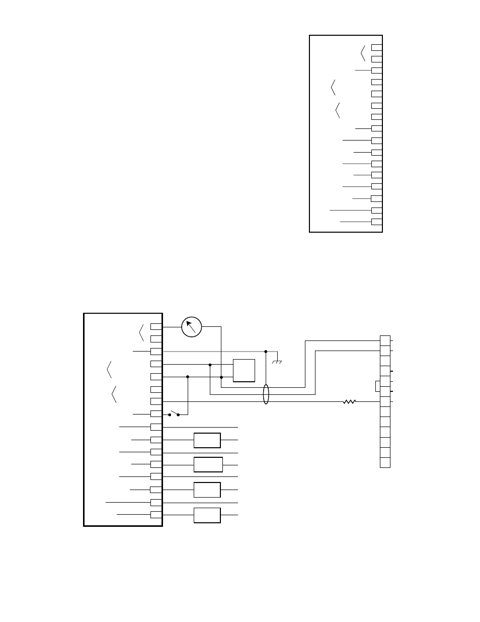
Figure 3 shows the terminal configuration for the R8471J
Controller.
Terminals 1 and 2 – 4 to 20 mA dc output.
non-Isolated current output -
If the 4 to 20 mA current loop
is to be non-isolated, wire the
system as shown in Figure 4.
Note that terminal 2 is not used
with a non-isolated current loop.
Program the unit for a non-isolated
current loop as described in the
“Controller Programming” section
of this manual.
Isolated current output - If an
isolated current loop is desired,
wire the system as shown in
Figure 5 and program the unit
for an isolated current loop as
described in the “Controller
Programming” section of this
manual. Note that this wiring
scheme requires an external
power source for the isolated
current output.
cUrrent oUtPUt
cHaSSIS GroUnD
PoWer
SenSor
external reSet
HIGH alarM
HIGH alarM / oc
aUx. alarM
aUx. alarM / oc
loW alarM
loW alarM / oc
FaUlt
FaUlt / oc
1
3
4
5
6
7
8
9
10
11
12
13
14
15
16
–
+
+
–
+
–
18 to 32
vDc
PoWer
SIGnal
2
oc = oPen collector oUtPUt
(BaSe MoDel onlY)
B190
Figure 3—Terminal Configuration for R8471J Controller
ISOLATED OUTPUT
CURRENT LOOP
CHASSIS GROUND
POWER
SENSOR
EXTERNAL RESET
HIGH ALARM
HIGH ALARM / OC
AUX. ALARM
AUX. ALARM / OC
LOW ALARM
LOW ALARM / OC
FAULT
FAULT / OC
1
3
4
5
6
7
8
9
10
11
12
13
14
15
16
–
+
+
–
+
–
18 TO 32VDC
GROUND
POWER
SIGNAL
HIGH
ALARM
AUXILIARY
ALARM
LOW
ALARM
FAULT
RESET
24
VDC
+
–
2
4-20 MA
A2412
R8471J CONTROLLER
*
*
*
NO CONNECTION
OC = OPEN COLLECTOR OUTPUT
(BASE MODEL ONLY)
–24 VDC
+24 VDC
– 4-20 MA
1
2
3
4
5
6
7
8
9
10
11
12
13
MODEL OPECL
GAS DETECTOR
+ 4-20 MA
–24 VDC
+24 VDC
2
1
NOTES: 1 INTERNAL JUMPER REQUIRED
FOR NON-ISOLATED CURRENT
OUTPUT (SINGLE POWER
SUPPLY).
2 250 OHM RESISTOR REQUIRED.
Figure 4—A Typical System with Relay Outputs and Non-Isolated Current Output