Faceplate description – Det-Tronics R8471J Single Channel Gas Controller, OPECL User Manual
Page 14
1.1
95-8572
12
Section II
Description and operating
characteristics
FACEPLATE DESCRIPTION
The faceplate of the controller provides LEDs for
identifying status conditions, a digital display and bar
graph display for indicating the OPECL input, and
pushbuttons for programming, calibrating and resetting
the system. See Figure 10 for the location of indicators
and pushbuttons.
1. Digital Display - In the Normal mode, the digital
display provides a continuous reading of the input
from the OPECL. An input signal less than 4 mA is
displayed as a negative reading by the controller.
An input signal greater than 20 mA is displayed as
an over-range reading by the controller.
In the event of a fault, the digital display identifies
the nature of the fault using an alpha-numeric code.
When the OPECL unit is in the calibrate mode, the
display tracks the calibration procedure. In other
operating modes it shows the alarm setpoints and
programmed calibration gas concentration. Since
this display is always lit, it also functions as a power
indicator.
2. Bar Graph Display - In the Normal mode, the 20
segment bar graph display provides a reading of
sensor input in increments of 5% full scale (each
bar represents 0.25 LFL-m).
3. High alarm leD - Flashes in response to a sensor
signal that exceeds the high setpoint.
4. auxiliary alarm leD - Flashes in response to a
sensor signal that exceeds the auxiliary setpoint.
5. low alarm leD - Flashes in response to a sensor
signal that exceeds the low setpoint.
NOTE
The alarm LEDs flash when the setpoint is
exceeded and are on steady (until reset) when
the gas level drops below the setpoint, whether
the corresponding alarm output is latching or
non-latching.
6. cal leD - Illuminated while the controller is in the
calibrate mode.
NOTE
In the Setpoint Display or Setpoint Adjust mode,
a flashing alarm LED identifies the particular
setpoint currently being indicated on the digital
display. A flashing Cal LED indicates that the
programmed calibration gas concentration (in %
full scale) is currently being shown on the digital
display.
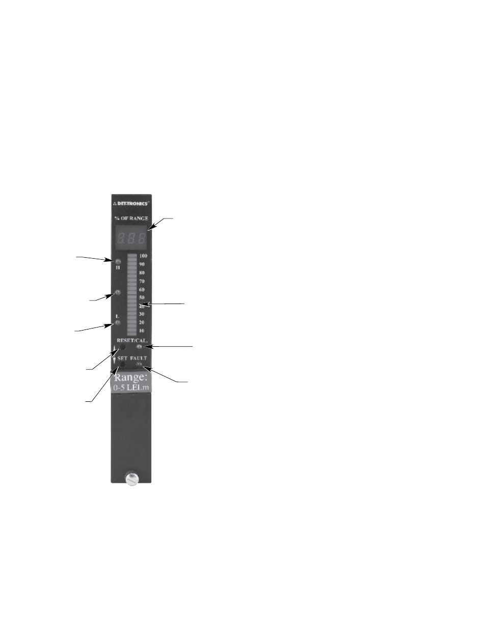
1
DIGITAL DISPLAY
2
BAR GRAPH
6
CAL LED
7
FAULT LED
A2416
8
RESET
PUSHBUTTON
9
SET
PUSHBUTTON
5
LOW LED
4
AUXILIARY LED
3
HIGH LED
Figure 10—Controller Front Panel