Det-Tronics R8471J Single Channel Gas Controller, OPECL User Manual
Page 4
1.1
95-8572
2
(a)
(B)
(c)
1.48 (37.59)
(D)
B1475
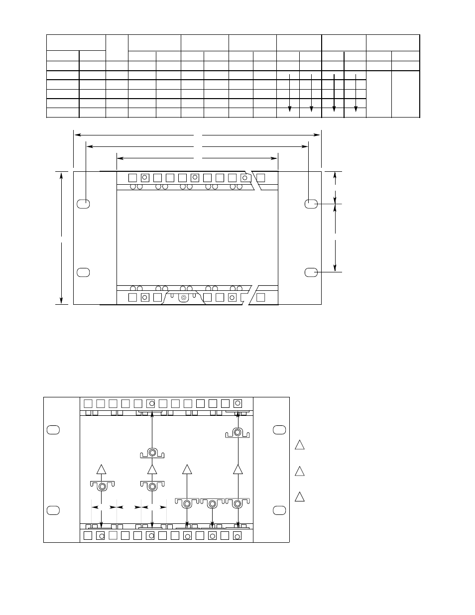
all controller caGeS reQUIre
a MInIMUM oF 10.12 IncHeS (257.1 MM)
DePtH clearance
(e)
Figure 1—Dimensions of the Q4004 Mounting Rack
1
A1476
FIre controllerS are aPProx. tWo IncHeS
WIDe anD reQUIre tWo GUIDe raIlS For
InSertIon. Place tHe retaInInG clIP BetWeen
raIlS to ForM SetS, leave a GaP BetWeen SetS.
Set
Set
GaP
1
2
3
2
tHe Q4004 controller caGe HaS Been MoDIFIeD
to accoMMoDate eItHer FIre or GaS controllerS
or anY coMBInatIon oF tHe tWo.
BY FolloWInG tHe InStrUctIonS BeloW, tHe caGe
can Be Set UP to anY conFIGUratIon.
2
to InSert a BlanK Panel, Place a clIP In
tHe toP BracKet In lIne WItH tHe clIP In tHe
BottoM BracKet.
3
GaS controllerS are aPProx. one IncH WIDe
anD reQUIre one raIl For InSertIon. Place clIPS
In lIne WItH GUIDe raIlS, caGeS WIll accePt aS
ManY GaS controllerS aS raIlS ProvIDeD.
Figure 2—Clip Positioning for Q4004 Mounting Racks
CONTROLLER
POSITIONS FOR
HT:
DIM. (A)
DIM. (B)
DIM. (C)
DIM. (D)
DIM. (E)
WEIGHT
FLAME GAS
INCH MM
INCH MM
INCH MM
INCH MM
INCH MM
LB
KG
8
16
4U
19.00 482.6
18.0 464.8
17.6 440.9
4.00 101.6
6.97 177.1
9.
4.2
6
12
4U
15.06 82.6
14.6 64.7
1.42 40.9
7.6
.5
4
8
4U
11.1 282.6
10.4 264.9
9.49 241.1
5.9
2.7
6
4U
9.16 22.7
8.46 214.9
7.52 191.0
5.1
2.
2
4
4U
7.19 182.7
6.49 164.9
5.55 141.0
4.2
1.9
1
2
4U
5.22 12.6
4.52 114.8
.58
90.9
.1
1.4
16
U
19.00 482.6
18.0 464.8
17.6 440.9
2.25 57.15
5.22 12.6
9.
4.2
12
U
15.06 82.6
14.6 64.7
1.42 40.9
7.6
.5
8
U
11.1 282.6
10.4 264.9
9.49 241.1
5.9
2.7
6
U
9.16 22.7
8.46 214.9
7.52 191.0
5.1
2.
4
U
7.19 182.7
6.49 164.9
5.55 141.0
4.2
1.9
2
U
5.22 12.6
4.52 114.8
.58
90.9
.1
1.4