Nuclear surveillance operation – Det-Tronics C7051B, C UV Flame Detector User Manual
Page 9
NUCLEAR SURVEILLANCE
OPERATION
The C7051 Detector includes two sensor modules
mounted on one base. The sensors are paired at the
factory for identical response to x-rays and gamma radi-
ation. One detector module is blinded to UV radiation
but detects nuclear radiation. The other detects both UV
and nuclear radiation. Both modules view the same
area. The blinded detector module is placed closer to
the radiation source than the fire detector, so that it
absorbs as much or more nuclear radiation as the fire
detector. Up to four C7051 assemblies can be used with
one R7404.
The count rate of the blinded detector module corre-
sponds to the intensity of nuclear radiation in the area to
be protected. The count rate of the fire detector module
corresponds to the intensity of the nuclear radiation plus
the UV radiation present in the protected area. The
blinded detector module’s count rate is subtracted from
the fire detector module’s count rate. The remainder cor-
responds to the UV radiation intensity in the protected
area. On the controller, zones one through four corre-
spond to fire detector modules and zones five through
eight correspond to surveillance detector modules. The
output of detector 5 is subtracted from detector 1, detec-
tor 6 from detector 2, and so on. Though the 5 - 1, 6 - 2,
7 - 3, and 8 - 4 pairs correspond to different detectors on
the controller, each pair corresponds to a single C7051
Detector. (See also the “System Sensitivity
Considerations” and “Switch Setting Procedure” sec-
tions.)
AUTOMATIC OPTICAL INTEGRITY
An important consideration with any UV fire detector is
that an accumulation of contaminants (oil, gasoline, dirt)
on the quartz window will absorb or block UV radiation.
Contamination on the window great enough to complete-
ly obscure UV from the detector can be virtually unde-
tectable to the human eye.
To ensure that the detectors are operational, the
Automatic
oi program continuously cycles through a test
of each detector module and its wiring. Both the blind-
ed and the unblinded modules of the C7051 Detector
incorporate a UV sensor tube and an optically isolated
UV test lamp.
In the unblinded module, actuation of the test lamp
causes UV radiation to travel out through the quartz win-
dow, where it encounters a reflective
oi ring and is
directed back through the window to the sensor tube. If
the window is clean, the sensor tube detects the UV from
the lamp and sends a signal back to the controller to ver-
ify that the detector module and its wires are functioning
properly. See Figure 5.
The blinded detector module is tested the same way,
except that only the sensor tube is tested, since there is
on quartz window to check.
The R7404 tests its detectors at the rate of approximate-
ly one per second, so that if a fault occurs, it is almost
instantly detected.
7
95-8256
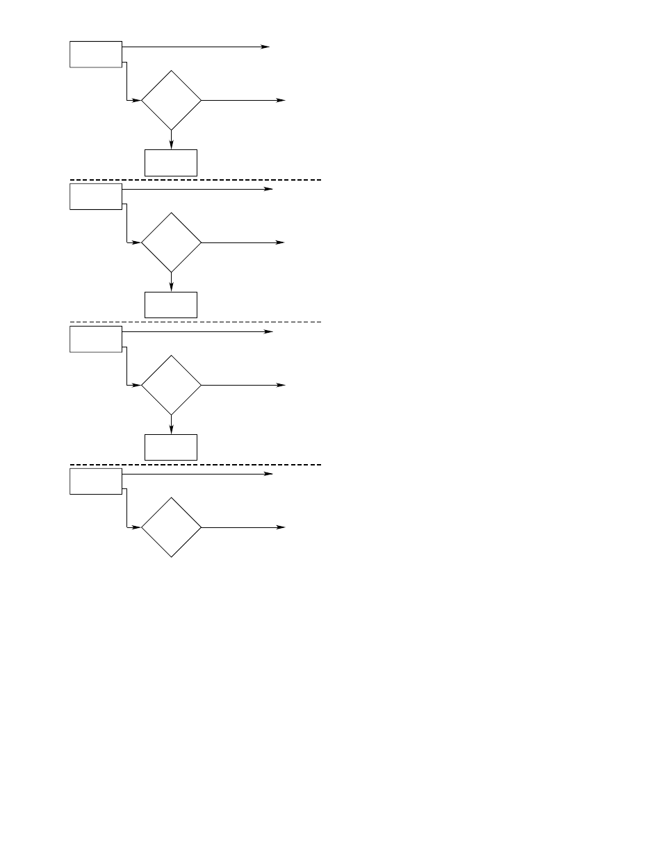
NO
NO FIRE LOGIC
OUTPUT
ANY ONE OR
MORE ZONES
SEE FIRE
ONE ZONE
SELECTED?
YES
FIRE
LOGIC
SELECTED
ZONE OUTPUT(S)
FIRE LOGIC
OUTPUT
A AND B
NO
NO FIRE LOGIC
OUTPUTS
ANY TWO OR
MORE ZONES
SEE FIRE
TWO ZONES
SELECTED?
YES
ZONE OUTPUTS
FIRE LOGIC
OUTPUT
A AND B
NO
NO FIRE LOGIC
OUTPUTS
ANY THREE OR
MORE ZONES
SEE FIRE
THREE ZONES
SELECTED?
YES
ZONE OUTPUTS
FIRE LOGIC
OUTPUT
A AND B
ANY FOUR OR
MORE ZONES
SEE FIRE
FOUR ZONES
SELECTED?
YES
ZONE OUTPUTS
FIRE LOGIC
OUTPUT
A AND B
Figure 4—Fire Logic Selection and Voting Sequence