Specifications – Det-Tronics C7051B, C UV Flame Detector User Manual
Page 11
2. Depress the TEST and SELECT buttons simultane-
ously and then release.
3. The STATUS display will show an “8” and the
DETECTOR and ZONE displays will show a “0” and
the number of the zone under test respectively.
The SELECT button serves the same function as in the
test mode described above. When the TEST button is
pressed, the UV test lamp in the selected detector is illu-
minated and the sensor sends a response back to the
controller. The DETECTOR and ZONE displays indicate
the response of the UV sensor under test (in cps). If the
FIRE LOGIC LEDs turn on, multiply the displayed count
by ten. The count rate should be between 50 and 300.
SPECIFICATIONS
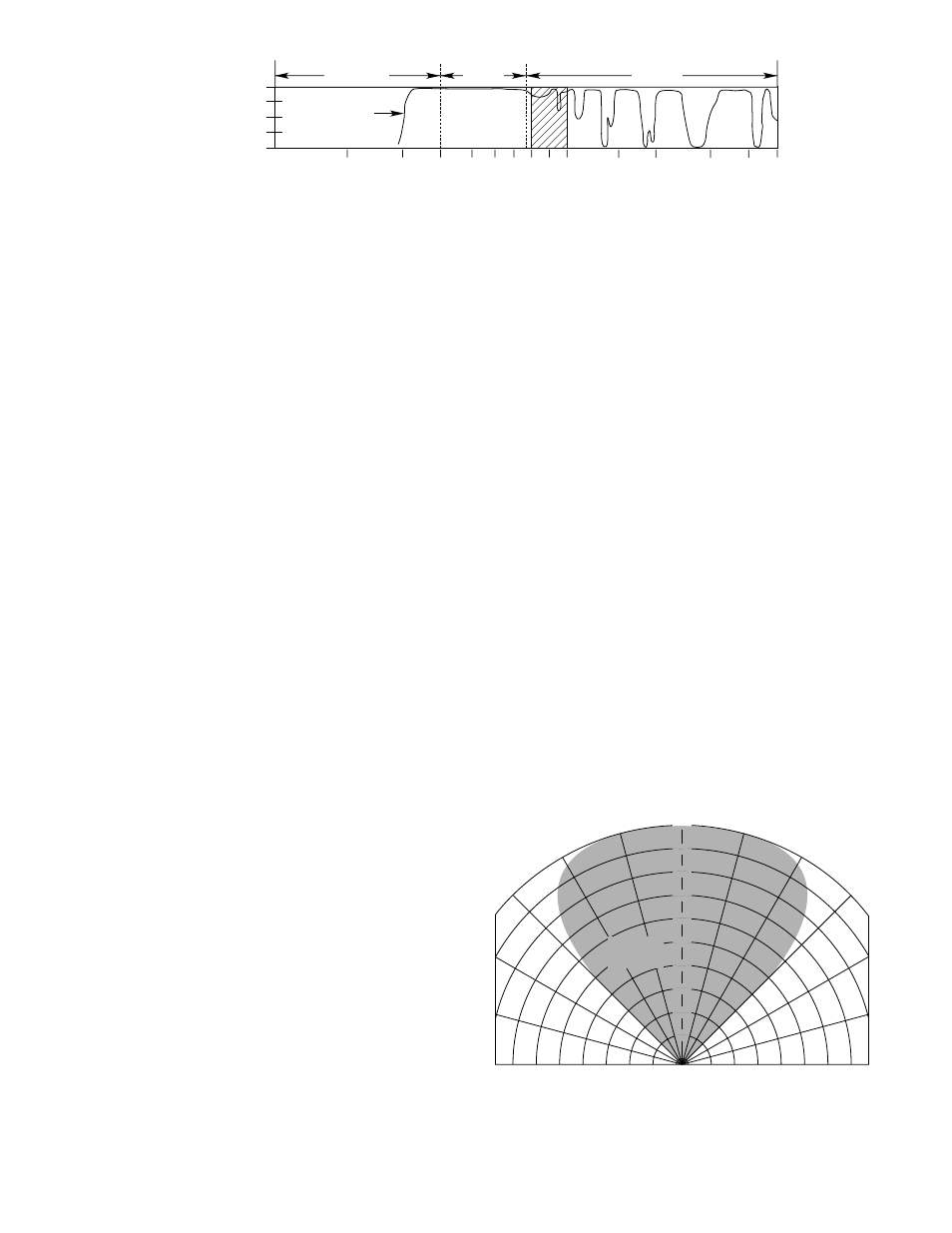
SPECTRAL SENSITIVITY RANGE—
Det-Tronics ultraviolet fire detectors respond to radiation
over the range of 1850 to 2450 Angstroms (see Figure 6).
Detectors are insensitive to direct or reflected sunlight
and to normal artificial lighting.
NOTE
High electrostatic forces will affect the detectors if
exposed directly at the window. Arc welding is an
intense UV source, and special application tech-
niques are required to restrict this radiation from the
detector’s cone of vision.
OPTICAL SENSITIVITY RANGE
(CONE OF VISION)—
The fire detector module of the C7051 Detector has a
nominal 90 degree cone of vision with the highest sensi-
tivity lying along its central axis. Figure 7 shows a com-
posite view of the cone of vision and the detector
response to a constant UV source at various relative dis-
tances. Depending upon the intensity of the UV radiation
source, the C7051 can be considered to have a practi-
cal application distance of up to about 50 feet (15
meters) when set to 24 cps. Since physical obstructions,
smoke accumulation or UV absorbing chemical vapors
will prevent UV from reaching the detectors, they should
be mounted as close as practical to the probable haz-
ard. Under certain controlled conditions, detectors may
be used at greater distances.
SYSTEM SENSITIVITY—
Sensitivity for R7404 Controllers is field adjustable over a
range of 8 through 120 counts per second (cps) in incre-
ments of 8 cps. The system should be set at no higher
a sensitivity than the minimum required for adequate
response to flame or explosion. The maximum response
distance (maximum sensitivity) is achieved at an 8 cps
sensitivity setting. For applications involving high back-
ground radiation potential, the system can be desensi-
tized by increasing the count rate required to actuate it.
The 120 cps setting (minimum sensitivity) results in the
minimum response distance.
NOTE
Setting the controller at maximum sensitivity and
minimum delay may increase the possibility of
false system actuation. Consult Detector
Electronics’ Customer Service department if such
a setting is desired.
9
95-8256
5.0
4.0
3.0
2.0
1.5
1.0
0.9
0.8
0.7
0.6
0.5
0.4
0.3
0.2
0.1
ATMOSPHERIC
TRANSMISSION
WAVELENGTH (MICRONS)
VISIBLE
INFRARED
ULTRAVIOLET
100
75
50
25
0
B1015
SOLAR RADIATION
REACHING THE EARTH
Figure 6—UV Detector’s Range of Sensitivity
0°
15°
30°
45°
15°
30°
45°
VIEWING ANGLE
100
90
80
70
60
50
40
30
20
10
DETECTION
DISTANCE
(PERCENT)
100% REPRESENTS THE MAXIMUM DETECTION DISTANCE FOR A
GIVEN FIRE. THE SENSITIVITY INCREASES AS THE ANGLE OF
INCIDENCE DECREASES.
Figure 7—Detector Cone of Vision