Typical system application, Startup procedure, Checkout procedure – Det-Tronics C7051B, C UV Flame Detector User Manual
Page 20
TYPICAL SYSTEM APPLICATION
The following application is an example only. For assis-
tance in adapting a system to your individual require-
ments, contact Application Engineering at Detector
Electronics.
The system illustrated in Figure 19 incorporates two con-
trollers that monitor eight detectors.
STARTUP PROCEDURE
CAUTION
Secure output loads before startup as described
in the “Manual Check in Normal Mode” subsec-
tion of the “Checkout Procedure.”
1. After setting the selection switches and making all
electrical connections, make sure that power is off
and plug controllers into connectors.
2. Turn on power and go through checkout proce-
dures.
3. If the controllers appear to be operating normally,
remove mechanical blocking devices and restore
power to the extinguishing loads.
CHECKOUT PROCEDURE
MANUAL CHECK OF OPTICAL INTEGRITY
1. Place keylock switch in TEST position.
2. FAULT LED turns on.
3. INHIBIT LED turns on.
4. ZONE display indicates the zone selected.
DETECTOR display shows a “0”.
5. STATUS display indicates a “1”. (If any other num-
ber appears, see “Troubleshooting” section.)
6. Push and hold TEST/ACCEPT button. If the lens is
clean, a ZONE OUTPUT LED flashes to indicate the
zone of the detector being tested (after time delay).
7. Appropriate FIRE LOGIC LEDs are turned on if vot-
ing requirements are met.
(Surveillance zones 5-8 are not voted on and will
not turn on FIRE LOGIC LEDs).
8. Release TEST/ACCEPT button, ZONE OUTPUT
LED remains on steady.
9. Push SELECT button. Controller sequences to the
next lower numbered zone.
10. Repeat steps 6 through 10 until all detectors have
been checked.
18
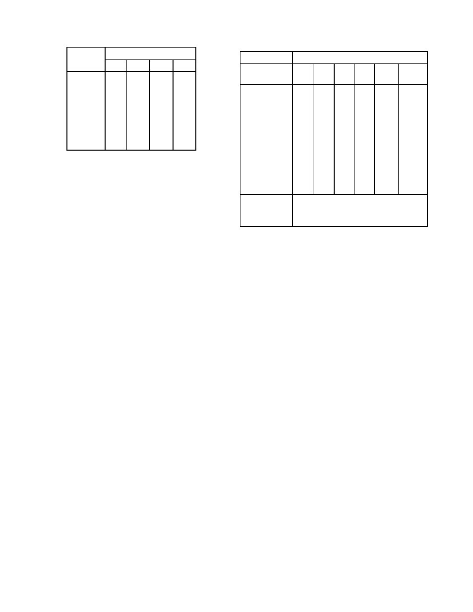
Zone
Status Outputs
S1
S2
S3
S4
1
1
0
0
0
2
0
1
0
0
3
1
1
0
0
4
0
0
1
0
5
1
0
1
0
6
0
1
1
0
7
1
1
1
0
8
0
0
0
1
Table 3—Relationship of ZONE Display to the
Status Outputs
Table 4—Relationship of SYSTEM STATUS Display
to Status Outputs
Front Panel Display
Status Outputs
Outputs
System Status
S5
S6
S7
S8
Fault
Inhibited
0
0
0
0
0
0
1
1
0
1
0
0
0
1
2
0
0
1
0
0
0
3
0
1
1
0
x***
0
4
0
0
0
1
0
0
5
0
1
0
1
0
0
6*
0
0
1
1
1
0
7**
0
1
1
1
1
0
8
0 or 1
0
0
0
0
1
9
1
1
0
0
0
1
Status Outputs
Logic 0 = 100k ohms to ground (0 volts)
S1 – S8, Fault
Logic 1 = Less than 25 ohms to ground
Outputs Inhibited
(0 volts)
Fire Zones only
Surveillance Zones only
1 on Fire Zones, 0 on Surveillance Zones
*
**
***