Det-Tronics C7051B, C UV Flame Detector User Manual
Page 19
It is inadvisable to use the minimum time delay (0.5
second) with the maximum detector sensitivity (8
cps), as this setting increases the possibility of
false system actuation.
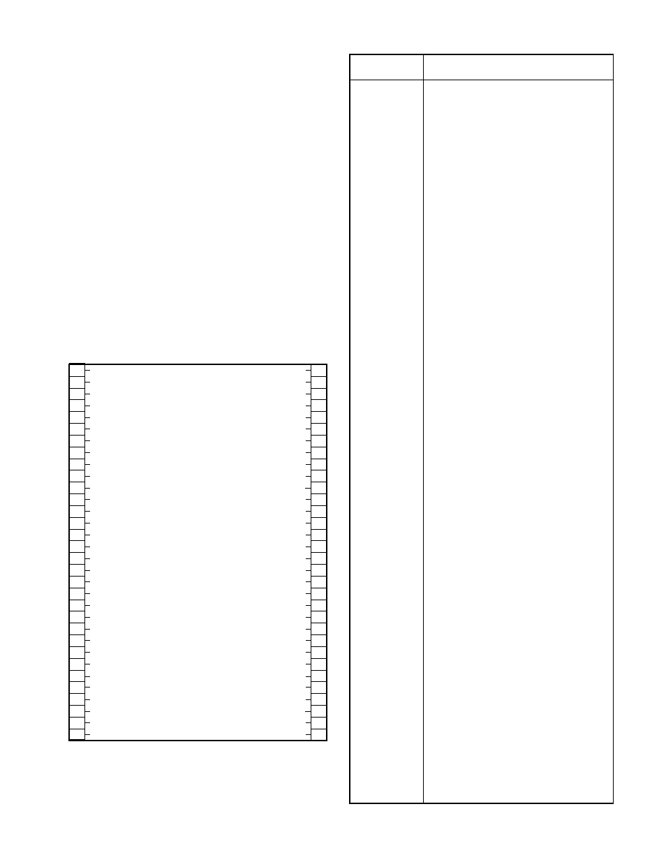
CONTROLLER ELECTRICAL CONNECTIONS
All electrical connections are made to the plug-in field
wiring connector that is furnished with the controller.
Figure 18 shows its terminal configuration. Table 2 lists
the terminal connections and a brief description of their
usage.
Up to four detectors in four separate zones can be con-
nected to the controller. Terminals A, B and D on the
detectors must be connected to the appropriate A, B
and D terminals at the R7404 Controller. Connect the
shield of the B-lead to terminal C in the detector and the
other end to circuit ground (terminal 2) at the controller
(see Figures 18 and 19). Terminal D in each detector
connects directly to individual terminals 12 through 19 on
the controller.
17
95-8256
1
2
3
4
5
6
7
8
9
10
11
12
13
14
15
16
17
18
19
20
21
22
23
24
25
26
27
28
29
30
31
32
+
–
(A) +290 VDC
B - INPUT 1
B - INPUT 2
B - INPUT 3
B - INPUT 4
B - INPUT 5
B - INPUT 6
B - INPUT 7
B - INPUT 8
D1-1 oi DRIVER
D1-2 oi DRIVER
D1-3 oi DRIVER
D1-4 oi DRIVER
D1-5 oi DRIVER
D1-6 oi DRIVER
D1-7 oi DRIVER
D1-8 oi DRIVER
DATA OUTPUT 0
DATA OUTPUT 1
DATA OUTPUT 2
DATA OUTPUT 3
DATA OUTPUT 4
DATA OUTPUT 5
DATA OUTPUT 6
DATA OUTPUT 7
DMA OUT AVAILABLE
DMA OUT
DMA IN
DATA STROBE
DMA IN AVAILABLE
ZONE OUTPUT 1
ZONE OUTPUT 2
ZONE OUTPUT 3
ZONE OUTPUT 4
NOT USED
NOT USED
LOW LEVEL ALARM
LOCKOUT OUTPUT
FIRE LOGIC
DATA SYNC
ALARM OUTPUT
EXTERNAL INHIBIT
OUTPUTS INHIBITED
FAULT OUTPUT
EXTERNAL ACCEPT
STATUS & DET. OUTPUT S1
STATUS & DET. OUTPUT S2
STATUS & DET. OUTPUT S3
STATUS & DET. OUTPUT S4
STATUS & DET. OUTPUT S5
STATUS & DET. OUTPUT S6
STATUS & DET. OUTPUT S7
STATUS & DET. OUTPUT S8
DATA BUS 0
DATA BUS 1
DATA BUS 2
DATA BUS 3
DATA BUS 4
DATA BUS 5
DATA BUS 6
DATA BUS 7
CHASSIS (EARTH) GND
33
34
35
36
37
38
39
40
41
42
43
44
45
46
47
48
49
50
51
52
53
54
55
56
57
58
59
60
61
62
63
64
J2
R7404
J1
10 TO 38 VDC
}
Figure 18—R7404 Nuclear Surveillance Controller
Terminal Configuration
Electrical
Terminals
Description
1 and 2
Input power: +10 to +38 vdc (1 to positive, 2
to circuit ground).
3
A-lead: (+290 vdc) connected to all detectors.
4 through 11
B-lead: input from each detector.
12 through 19
D- lead:
oi driver to each detector.
20 through 27
Data Bus terminals - data transfer outputs,
connected to the data input bus of the (next)
surveillance controller in the series.
28 through 32
DMA (direct memory access) and data strobe
terminals. DMA IN (terminal 30) is connected
to the data sync output of the last surveillance
controller in the series.
33 through 36
Solid State Zone Outputs: correspond to four
fire zones (reference to ground - terminal 2).
NOTE: All R7404 solid state outputs are rated
100 ma at 0.5 volt when “on” (low state). The
outputs are high impedance (open collector,
100K ohm) when “off” (high state). Only the
Fault output is normally “on.”
37, 38
Not used.
39
Low level alarm output – count rate has
exceeded 50% of sensitivity setting.
40
Solid state “lockout” output – activated by con-
troller to indicate saturation lockout condition.
41
Solid State Fire Logic output – see “Theory of
Operation.”
42
Data Sync output – connects to DMA IN of
slave controller.
43
Solid State Alarm output – activated whenever
any zone output is activated. It is a latching
output and can be deactivated by depressing
the TEST/ACCEPT button or by activating the
external accept input (see below).
44
External Inhibit (input) – when activated, resets
the controller and disables fire response out-
puts. Input is activated when shorted to
ground (-V, terminal 2).
45
Solid State Outputs Inhibited (output) – is acti-
vated when fire response outputs are disabled.
46
Solid State Fault output – Normally “on” (low
voltage - logic 1), turned off by controller to
indicate a fault status.
47
External Accept (input) provides a means to
deactivate the alarm output. Input is activated
when shorted to ground.
48 through 55
Solid State Status and Detector outputs – pro-
vide binary representations of the front panel
digital displays for zone and status identifica-
tion. Tables 3 and 4 list the identification
codes and the logic states of the “Fault” and
“Outputs Inhibited” bits for the various status
conditions.
56 through 63
Data Bus terminals – data transfer inputs, con-
nected to the data output bus of the last sur-
veillance controller in the series.
64
Chassis (earth) ground – should be connected
to circuit ground (terminal 2) through a 0.47 µF
400 Volt non-polarized capacitor (not supplied).
Table 2—Nuclear Surveillance Controller Terminal Connections