Det-Tronics C7051B, C UV Flame Detector User Manual
Page 6
R7404 CONTROLLER
Microprocessor technology has made possible a degree
of programming flexibility that could not be achieved in
previous generations of Det-Tronics systems. The R7404
Controller incorporates a microprocessor and a pro-
grammable memory to store and implement the perma-
nent program for operating the system. The operating
program continuously cycles through the Automatic
Optical Integrity test, checking each detector and its
wiring. The microprocessor can be interrupted by any
one of several status changes, such as a fault, a UV sig-
nal from one of the C7051 Detectors, or a change in the
setting of the keylock switch. In the event of a status
change, the microprocessor will react to the change.
The output of the controller is interpreted by other sur-
veillance/fire detection controllers in the system for vot-
ing purposes. The controller provides solid state outputs
that are activated in response to fire signals from the
C7051 Detectors, and to status occurrences such as
system faults.
In the nuclear surveillance system, fire detection and sur-
veillance functions are controlled by the same R7404
Controller. The operating program of each R7404 deter-
mines its wiring and switch setting configuration as well
as its mode of operation.
Front Panel
The front panel of the R7404 Controller (Figure 3) pro-
vides switches and indicators to enable manual
oi and
data bus tests (see “Checkout Procedure”) and to iden-
tify output actuation and status occurrences.
1. The green POWER LED is illuminated whenever
power is applied to the controller.
2. The amber FAULT LED is illuminated in the event of
a system malfunction or an undesirable status
occurrence (see “Theory of Operation - Fault
Identification”).
3. The amber INHIBIT LED is illuminated when the
controller is reset or placed in the test mode. It
indicates that all solid state outputs are disabled.
(See “Theory of Operation” and “Installation” sec-
tions.)
4. The red FIRE LOGIC A and B LEDs are illuminated
when the solid state fire logic outputs are actuated.
(See “Theory of Operation”.)
5. The eight ZONE OUTPUT LEDs correspond to the
eight detector inputs. See “Theory of Operation”
for details. The ZONE OUTPUT LEDs are red for
the fire protection zones and green for the remote
surveillance zones.
6. The upper digital display on the front panel identi-
fies the number of the zone involved in any system
status occurrence on the ZONE display. Since the
nuclear surveillance system is restricted to one
detector per zone, the DETECTOR display will
show a “0” whenever it is activated. (See “Theory
of Operation.”)
7. The lower digital display identifies by code number
system status occurrences such as fire or fault con-
ditions. Table 1 is a list of the status codes and
their interpretations.
4
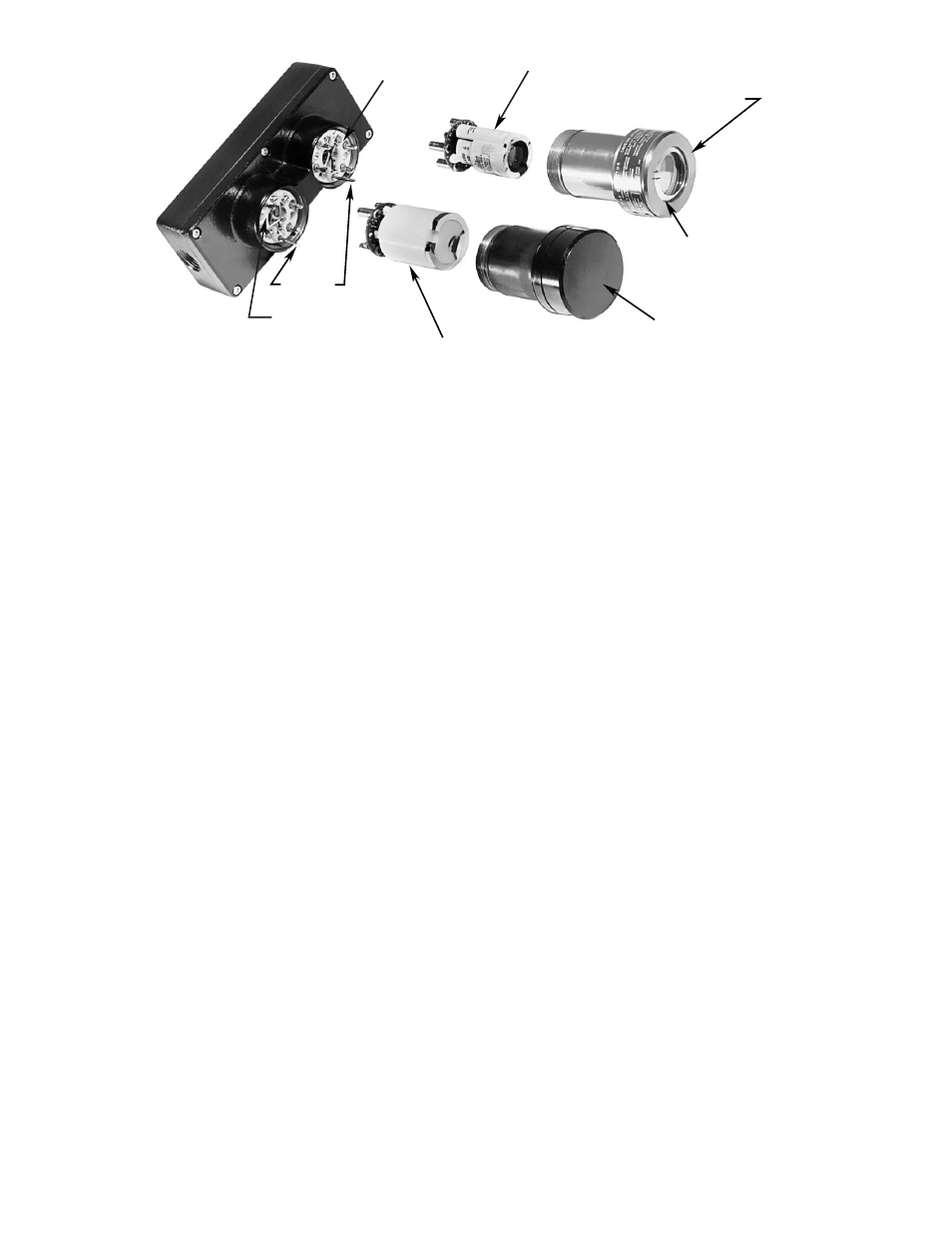
QUARTZ WINDOW AND HOUSING
TERMINAL BLOCK
TERMINAL BLOCK
INDEX PIN
Oi REFLECTIVE RING
BLINDED WINDOW
UV DETECTOR TUBE
RADIATION DETECTOR TUBE
Figure 2—C7051 Detector Assembly