System description – Det-Tronics C7051B, C UV Flame Detector User Manual
Page 5
Nuclear radiation is also a potential cause of false actu-
ation of the detection system. X-rays and gamma radia-
tion easily penetrate the metal housing of the detectors,
causing the UV sensor tubes to react in the same way as
they would to UV radiation. While the nuclear surveil-
lance system compensates for x-rays and gamma radia-
tion present in the protected area, care must be taken
that the C7051 Detectors are aligned in such a way that
the blinded detector sections are between the nuclear
radiation source and the UV detector sections. If the
blinded detector section intercepts less nuclear radiation
than the fire detector section, false system actuation can
result. Consult “Installation” section for further details.
An important fact regarding UV detectors of any type is
that ultraviolet radiation must reach the detectors in order
for them to respond. Care must be taken to keep
obstructions out of the line of view. For a UV detector,
this means that ultraviolet absorbing gases or vapors as
well as physical obstructions must not be allowed to
come between the detector and the protected hazard.
Smoke will absorb UV radiation, and if accumulations of
dense smoke can be expected to precede the presence
of flame, then UV detectors should not be used alone.
It must be noted that malfunctions can occur in any type
of equipment, and although Det-Tronics systems are
subjected to rigorous tests before shipment, no way has
yet been found to guarantee that every device will
always operate perfectly. The highest reliability with
regard to response to a fire is achieved when a haz-
ardous area is supervised by more than one detector,
and when each detector can independently register an
alarm.
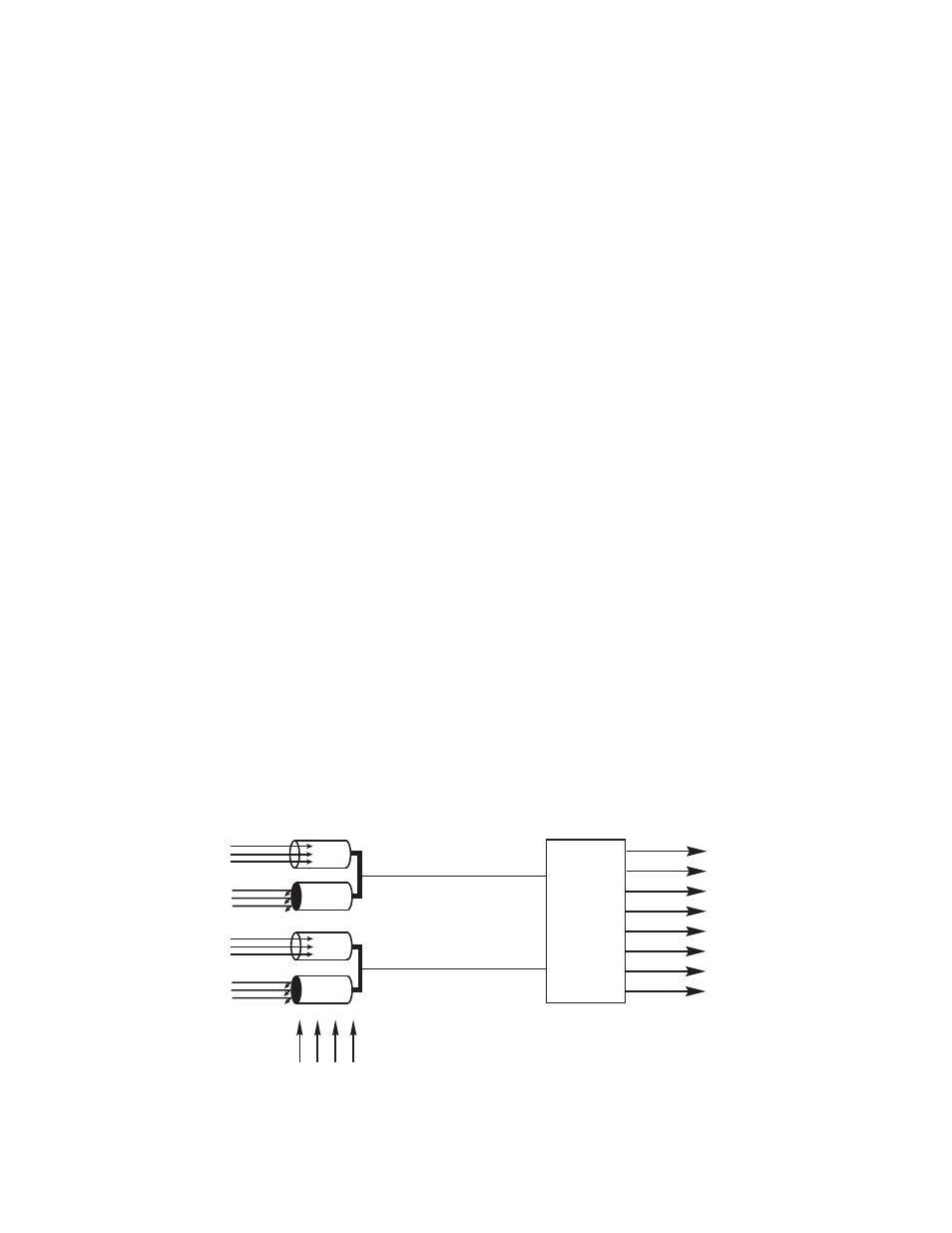
SYSTEM DESCRIPTION
The nuclear surveillance system consists of one to four
R7404 Controllers that are wired and programmed to
monitor up to sixteen C7051 UV/nuclear radiation detec-
tors.
Each controller can accommodate up to four C7051
Detectors. Figure 1 is a simplified diagram of a nuclear
surveillance system.
C7051 DETECTOR
The C7051 Detector (Figure 2) incorporates two Det-
Tronics C7050 type UV detector modules. Each module
holds a Geiger-Muller type sensor tube, circuitry to
process and transmit an output signal, and a UV test
lamp (“source tube”) which is used to test the sensor
tube. The two sensor tubes are sent from the factory as
a matched pair; both are selected for their identical
response to UV and nuclear radiation. One detector
module is blinded to UV; both are responsive to x-ray
and gamma radiation. When UV or nuclear radiation
strikes the cathode of the sensor tube, a series of voltage
pulses is sent to the controller. The frequency of the
pulses is proportional to the intensity of the UV or nuclear
radiation. Each detector module is connected to the
controller by three wires (see “Installation”). The wires
are referred to as A-, B-, and D- leads.
1. The A- lead is connected to the +290 vdc supply.
2. The B- lead is the “signal” line (sensor tube to con-
troller).
3. The D- lead is the test lamp control line.
Each module is housed in an explosion-proof enclosure
designed to meet most national and international stan-
dards.
NOTE
It is required that the C7051 Detector housing be
connected to earth ground to avoid the possibility of
false detector actuation in areas with high electro-
static potential. A grounding lug is provided for this
purpose at the junction box.
3
95-8256
FIRE
FIRE
BLINDED
BLINDED
FIRE
CONTROLLER
DETECTOR
DETECTOR
C7051
C7051
NUCLEAR
RADIATION
BLINDED DETECTOR
SIGNAL IS SUBTRACTED
FROM FIRE DETECTOR
SIGNAL
SOLID
STATE
OUTPUTS
UV
UV
UV
UV
Figure 1—Simplified Block Diagram - Nuclear Surveillance System