Det-Tronics C7051B, C UV Flame Detector User Manual
Page 17
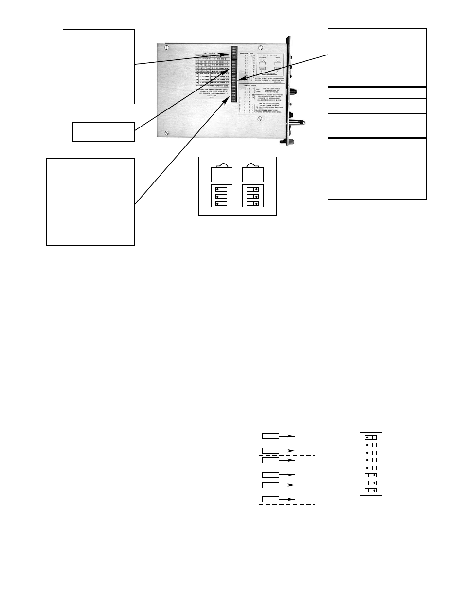
1. Detectors Connected — Switch Assembly Rockers
1-1 to 1-4. Each zone can have one detector for a
maximum of four detectors in four zones connect-
ed to one controller. (The word “detector” denotes
the C7051, which comprises two detector modules,
in this context.) Switch assembly rockers 1-1
through 1-4 are used to enable the detector of
each zone. The appropriate rocker must be set to
the “Open” position for each detector connected.
Care must be taken when setting these rockers. If
a rocker is set open, but no detector is connected
in that location , the controller will show a “2-fault”
on the lower digital display and the ZONE display
will show which zone is set incorrectly. If a rocker
is set closed, but a detector is connected, the con-
troller performs normally, but that detector is elimi-
nated from the Automatic
oi test sequence, and
any faults that may occur in its circuit would not be
automatically identified. This condition can be
found only when performing the manual
oi test pro-
cedure. See the “Troubleshooting” section. Figure
13 is an example of switch settings for a controller
using three detectors.
2. Switch Assembly Rockers 2-1 to 2-8 are not used.
3. Controller Sensitivity Adjustment — Switch
Assembly Rockers 3-1 to 3-4 are used to set (pro-
gram) controller sensitivity in 8 cps increments.
3-1 closed - 8 cps
3-2 closed - 16 cps
3-3 closed - 32 cps
3-4 closed - 64 cps
Sensitivity = cumulative value of rockers set closed
These rockers may be set in any combination to
give the sensitivity setting selected for the applica-
tion, up to 120 cps.
15
95-8256
SWITCH ROCKER NUMBERS ARE DESIGNATED 1-1, 1-2, 1-3, ETC.
THE NUMBER PRECEDING THE DASH INDICATES THE SWITCH NUMBER.
THE NUMBER FOLLOWING THE DASH INDICATES THE ROCKER NUMBER
OF THE SWITCH INDICATED.
NOTE:
8
7
6
OPEN
8
7
6
OPEN
DOT INDICATES ROCKER DEPRESSED
ROCKER POSITIONS
CLOSED
OPEN
SWITCH ASSEMBLY 1
DETECTOR PAIR SELECTION
ROCKER 1-4 OPEN:
ZONES 4 AND 8 SELECTED
ROCKER 1-3 OPEN:
ZONES 3 AND 7 SELECTED
ROCKER 1-2 OPEN:
ZONES 2 AND 6 SELECTED
ROCKER 1-1 OPEN:
ZONES 1 AND 5 SELECTED
SWITCH ASSEMBLY 4
TIME DELAY AND
LATCHING/NON-LATCHING OUTPUTS
ROCKER 8 – NOT USED
ROCKER 7 – NOT USED
ROCKER 6 – 4 SECOND DELAY
ROCKER 5 – 2 SECOND DELAY
ROCKER 4 – 1 SECOND DELAY
ROCKER 3 – 0.5 SECOND DELAY
ROCKER 2 – 0.25 SECOND DELAY
(ALL SWITCHES OPEN,
TIME DELAY = 0.5 SECOND)
ROCKER 1 – LATCHING OUTPUTS
WHEN ROCKER IS OPEN
SWITCH ASSEMBLY 2
NOT USED
SENSITIVITY SELECTION
ROCKER 3-4 CLOSED = 64 CPS
ROCKER 3-3 CLOSED = 32 CPS
ROCKER 3-2 CLOSED = 16 CPS
ROCKER 3-1 CLOSED = 8 CPS
(ALL ROCKERS OPEN
OR ROCKER 3-1 CLOSED = 8 CPS)
THESE ROCKERS MAY BE USED
IN ANY COMBINATION FOR 8 CPS TO 120 CPS
3-7
3-6
ALL OPEN
1 CLOSED
2 CLOSED
3 CLOSED
3-5
ON (FOR 1 OF 4 ZONES)
ON (FOR 2 OF 4 ZONES)
ON (FOR 3 OF 4 ZONES)
ON (FOR 4 OF 4 ZONES)
FIRE LOGIC OUTPUTS
ROCKER POSITION
FIRE LOGIC SETTING
SWITCH ASSEMBLY 3
MASTER/SLAVE SELECTION
ROCKER SWITCH 3-8 OPEN:
SLAVE – ALL SURVEILLANCE
CONTROLLERS EXCEPT
FIRST IN SERIES
ROCKER SWITCH 3-8 CLOSED:
MASTER – FIRST SURVEILLANCE
CONTROLLER IN SERIES
Figure 12—Controller Rocker Switches
8
7
6
5
4
3
2
1
DETECTORS
NOT USED
SWITCH 1
{
FIRE
INPUT 3
INPUT 7
BLIND
FIRE
INPUT 2
INPUT 6
BLIND
FIRE
INPUT 1
INPUT 5
BLIND
SWITCH OPEN = DETECTOR SELECTED
INPUTS 1 - 3 (FIRE) AND
5 - 7 (RADIATION) SELECTED
C7051
C7051
C7051
OPEN
Figure 13—Detector Selection