Det-Tronics C7051B, C UV Flame Detector User Manual
Page 18
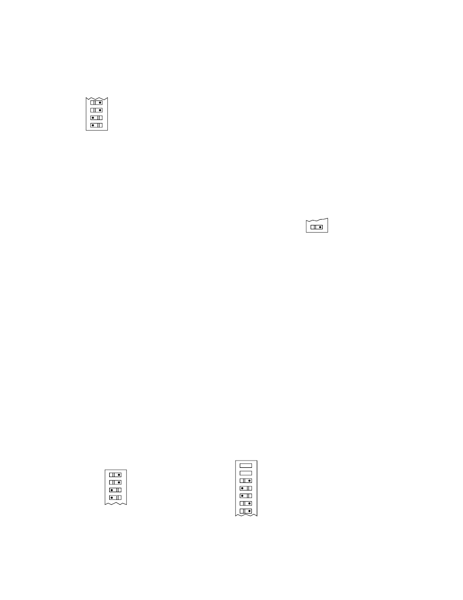
NOTE
If no rockers are closed, or if only rocker 3-1 is
closed, the controller responds to an 8 cps signal
from the detector.
Figure 14 is an example of a 24 cps setting.
4. Fire Logic Voting Criteria — Switch Assembly
Rockers 3-5 to 3-7, Rockers 3-5, 3-6 and 3-7 select
the voting requirements, which are Fire Logic A
and B common (4 zones voting).
NOTE
When the outputs are set for non-latching opera-
tion, the voting process will actuate the Fire Logic
outputs only if the preselected number of voting
zones “see” fire at the same time. When the out-
puts are set for latching operation, the voting
process will actuate the Fire Logic outputs when
voting criteria have been met, even if fire is not
being seen by each voting zone at the same time.
Zones 5 through 8 do not latch.
— Rockers 3-5, 3-6 and 3-7 open - one of four zones is
required for actuation.
— Rocker 3-5 closed, rockers 3-6 and 3-7 open - two of
four zones are required for actuation.
— Rockers 3-5 and 3-6 closed, rocker 3-7 open - three
of four zones are required for actuation.
— Rockers 3-5, 3-6 and 3-7 closed - four of four zones
are required for actuation.
In the example illustrated in Figure 15 the setting is for
three of four zones voting.
Switch 3-8 selects master or slave operation for the con-
troller.
Closed = master, Open = slave.
5. Outputs Latching/Non-Latching - Switch Assembly
Rocker 4-1.
Closed = Non-Latching
Open = Latching
NOTE
The zone and fire logic outputs will latch when
turned on if rocker 4-1 is set open.
The outputs are de-latched by placing keylock
switch in RESET position or by actuating the
External Inhibit input. Figure 16 shows the setting
for selecting latching outputs.
6. Time Delay — Switch Assembly Rockers 4-2, 4-3,
4-4, 4-5 and 4-6. The time delay switches have the
following values.
Rocker 4-2
0.25 second
Rocker 4-3
0.5 second
Rocker 4-4
1.0 second
Rocker 4-5
2.0 seconds
Rocker 4-6
4.0 seconds
The total time delay is the added value of the rock-
ers in the closed position plus 0.5 second.
Rockers can be closed in any arrangement for a
time delay of 0.5 to 8.25 seconds in 0.25 second
intervals.
Figure 17 shows the switch setting for a time delay
of 3.5 seconds.
16
4
3
2
1
OPEN
3-1 CLOSED = 8 CPS
3-2 CLOSED = 16 CPS
TOTAL SENSITIVITY = 24 CPS
SWITCH 3
A0281
Figure 14—Controller Sensitivity Selection
8
7
6
5
3 OF 4 ZONES VOTING
SWITCH 3
OPEN
Figure 15—Fire Logic Voting Selection
OPEN
SWITCH 4
OUTPUTS LATCHED
1
Figure 16—Latching/Non-Latching Output Selection
8
7
6
5
4
3
2
OPEN
NOTE: THE VALUE OF ROCKERS SET IN THE CLOSED POSITION ARE ADDITIVE.
4 SECOND TIME DELAY
2 SECOND TIME DELAY
1 SECOND TIME DELAY
0.5 SECOND TIME DELAY
0.25 SECOND TIME DELAY
}
NOT USED
ROCKER 5 CLOSED = 2 SECONDS
ROCKER 4 CLOSED = 1 SECOND
TOTAL TIME DELAY = 3.5 SECONDS
SWITCH 4
Figure 17—Time Delay Selection