Det-Tronics C7051B, C UV Flame Detector User Manual
Page 16
Connect the B-lead shields to connector C in the termi-
nal block. All A-leads go to the A-lead connection in the
terminal block. If one C7051 is used, its fire detector
module is connected to zone 1 B-lead and D-lead inputs,
and its blinded detector module is connected to zone 5
B-lead and D-lead inputs. A second C7051’s fire and
blinded detector module would be connected to zones 2
and 6 respectively. Zones 1 to 4 on the backplate con-
nect to fire detector modules. Zones 5 to 8 connect to
blinded surveillance detector modules. Up to four
C7051s can be connected to one R7404.
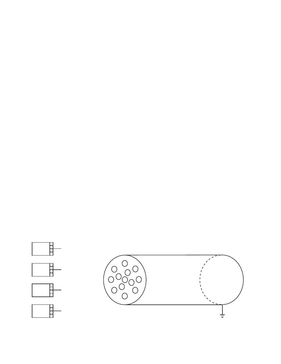
NOTE
If the wires from individual detectors are connect-
ed to the R7404 Controller in a multiple conduc-
tor cable, it is necessary to arrange them as
shown in Figure 11 to prevent “cross-talk.” The
individual B-leads should be arranged around the
outside of the cable with a ground lead between.
The inner layer of conductors should be the D-
leads with the common A-lead in the center.
These instructions apply for installations using
from two to four detectors.
5. Remove matched UV sensor tube modules from
shipping package and place into position on blind-
ed and fire detector terminal blocks, locating the
correct terminal position by observing the index
pin. Avoid touching the exposed glass envelopes
of the tubes, since oil from fingerprints can absorb
UV and reduce the tube’s sensitivity.
NOTE
Use only specially matched pairs of DE1888G2
tube modules in R7404/C7051 systems.
6. Install four screws on each detector and tighten.
7. On blinded detector module, slide
oi reflector cap
over barrel of sensor tube module until firmly seat-
ed. Make certain semicircular opening is centered
exactly over source tube on sensor tube module.
8. Replace detector housings. Black anodized barrel
is screwed onto blinded detector module. Red
barrel is screwed onto fire detector module.
9. Thoroughly clean the fire detector window and the
reflective ring. Det-Tronics window cleaner solution
is specially designed for this application. Many of
the commercial cleaners leave a residue on the
surface that absorbs UV radiation. Clean the win-
dow out to the edge. After cleaning, re-install the
ring so the split is 180 degrees from the
oi test
lamp (opening down to prevent water buildup).
Hold the ring by the tabs, being careful not to leave
fingerprints on the reflective surface.
NOTE
Use a clean cloth for cleaning. DO NOT use
commercial glass cleaning tissues since many of
these contain a silicone substance, which
remains on the cleaned surface and will absorb
UV radiation.
SWITCH SETTING PROCEDURE
It is essential that the controllers are properly pro-
grammed at the time of installation. There are three rock-
er switch assemblies on the left side of each controller
that are used to select detectors, controller sensitivity,
fire logic (voting), output latching and time delay.
Figure 12 illustrates the left side of the R7404 Controller
and contains a short explanation of rocker switch usage.
14
A
B
C
D
DETECTOR 1
A
B
C
D
DETECTOR 2
A
B
C
D
DETECTOR 3
A
B
C
D
DETECTOR 4
G
G
G
G
B1
B2
B3
B4
D1
D2
D3
D4
A
Figure 11—Wire Arrangement in a Multiple Conductor Cable