Switch setting procedure – Det-Tronics U7602E Unitized UV Flame Detector/Controller User Manual
Page 8
SWITCH SETTING PROCEDURE
Before the electronic module can be installed, the DIP
switches on the module must be set. Refer to Figure 9
for location of switches and Table 2 for switch positions
and functions. Switch is “off” when switch position is
toward the circuit board.
Set the switches as desired, then record the switch
settings for future reference.
IMPORTANT
Proper configuration is vital to successful
application. Configuration determines the
balance between false alarm resistance and
flame sensitivity. Use of excess sensitivity may
result in false alarms, while too little sensitivity
may cause target fires to be missed. Use of
arc rejection is recommended except when
extremely high speed response is required.
SW-1
Operating Mode
The operating mode determines the type
of logic that the UV flame detector will use
for processing fire signals (either
standard or arc rejection).
Standard Mode
In the standard processing mode, the
detector output (measured in counts per
second) is compared to the fire threshold
(the “sensitivity” setting as described
below). If the radiant energy level from
the fire exceeds the selected alar m
threshold level, the time delay begins (if a
time delay is selected). If the radiant
energy level from the fire remains above
the selected sensitivity level for the
duration of the time delay, the fire alarm
output is activated. In every application,
it is crucial to ensure that the radiant
ultraviolet energy level from the expected
fire at the required distance from the
detector will exceed the selected
sensitivity level.
Standard signal processing is
recommended for applications where
background electrostatic energy has
been verified to be absent.
6
JUMPE
+
–
24 VDC
4 TO 20 MA
FIRE ALARM
PANEL
A184
U7602E
11
12
13
14
1
2
3
4
+
–
4 TO 20
MA
–
+
875 Ω MAX
AT 24 VDC
Figure 7—Detector Wired for Non-Isolated 4 to 20 ma
Current Output (Sourcing)
JUMPER
24 VDC
4 TO 20 MA
FIRE ALARM
PANEL
A1849
U7602E
11
12
13
14
1
2
3
4
+
–
4 TO 20
MA
JUMPER
+
–
24 VDC
–
+
+
–
875 Ω MAX
AT 24 VDC
Figure 8—Detector Wired for Isolated 4 to 20 ma
Current Output (Sinking)
95-8465
+
–
24 VDC
ALARM
11
12
13
14
15
16
17
18
19
20
1
2
3
4
5
6
7
8
9
10
EOL
DEVICE
FIRE ALARM PANEL
*
FAULT RELAY IS SHOWN DE-ENERGIZED, BUT IS NORMALLY ENERGIZED WITH POWER APPLIED AND NO FAULTS PRESENT
C1515
U7602E
oi
TEST
U7602E
11
12
13
14
15
16
17
18
19
20
1
2
3
4
5
6
7
8
9
10
+
–
4 TO 20 MA
oi
oi
*
FAULT
*
FAULT
FIRE
FIRE
+
–
+
–
+
–
+
–
+
–
+
–
+
–
REF
REF
4 TO 20 MA
U7602E
11
12
13
14
15
16
17
18
19
20
1
2
3
4
5
6
7
8
9
10
+
–
4 TO 20 MA
oi
*
FAULT
FIRE
+
–
+
–
+
–
REF
0.47µF/400 VOLT
CAPACITOR
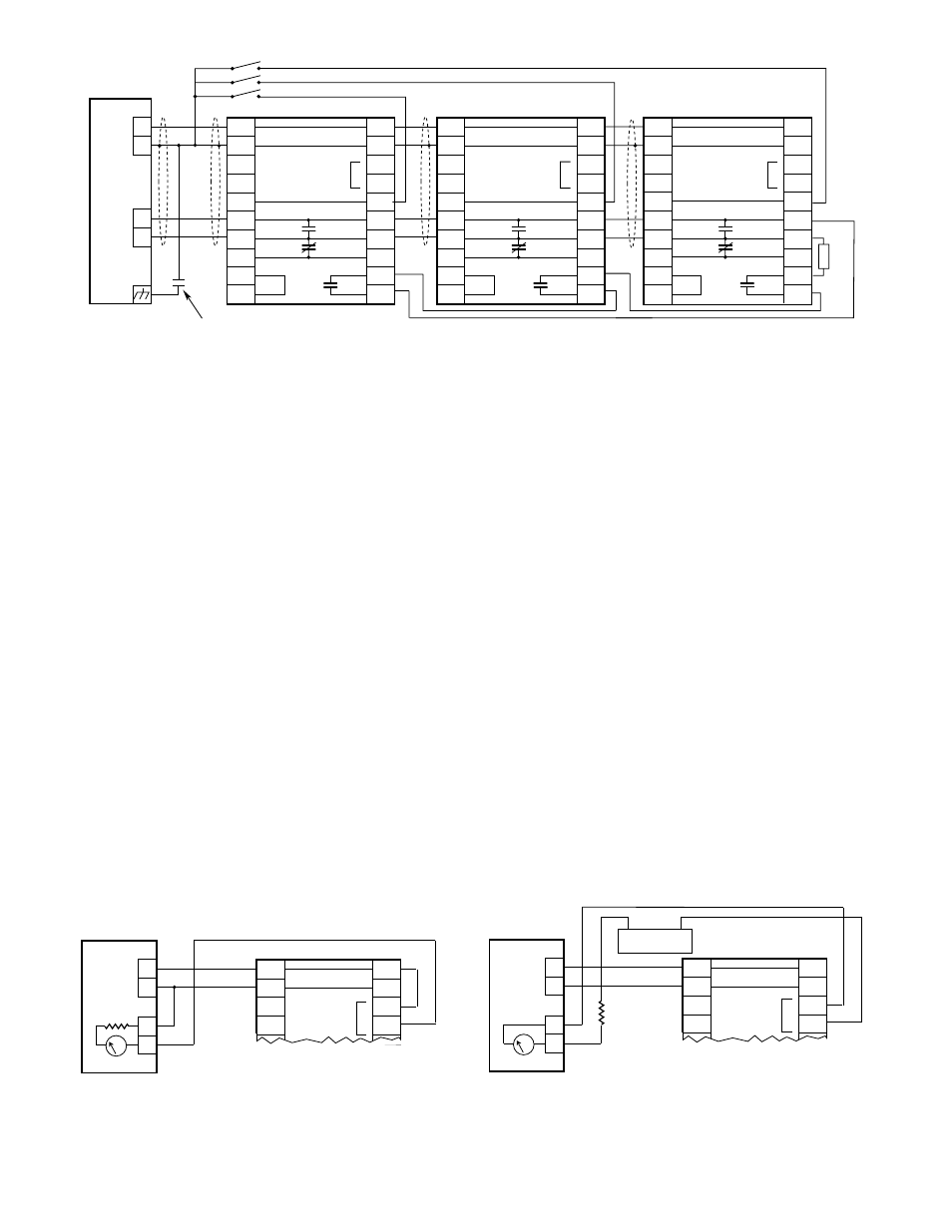
Figure 6—A Typical System