Installation – Det-Tronics U7602E Unitized UV Flame Detector/Controller User Manual
Page 5
INSTALLATION
DETECTOR POSITIONING
Detectors should be positioned to provide the best
unobstructed view of the area to be protected. The
following factors should also be taken into consideration:
• Identify all high risk fire ignition sources.
• Be sure that enough detectors are used to adequately
cover the hazardous area.
• Locate and position the detector so that the fire
hazard(s) are within both the field of view and
detection range of the device. Refer to Appendix A
for specific information.
• Be sure that the unit is easily accessible for cleaning
and other periodic servicing.
• Particular attention should be paid to potential false
alarm sources in the area.
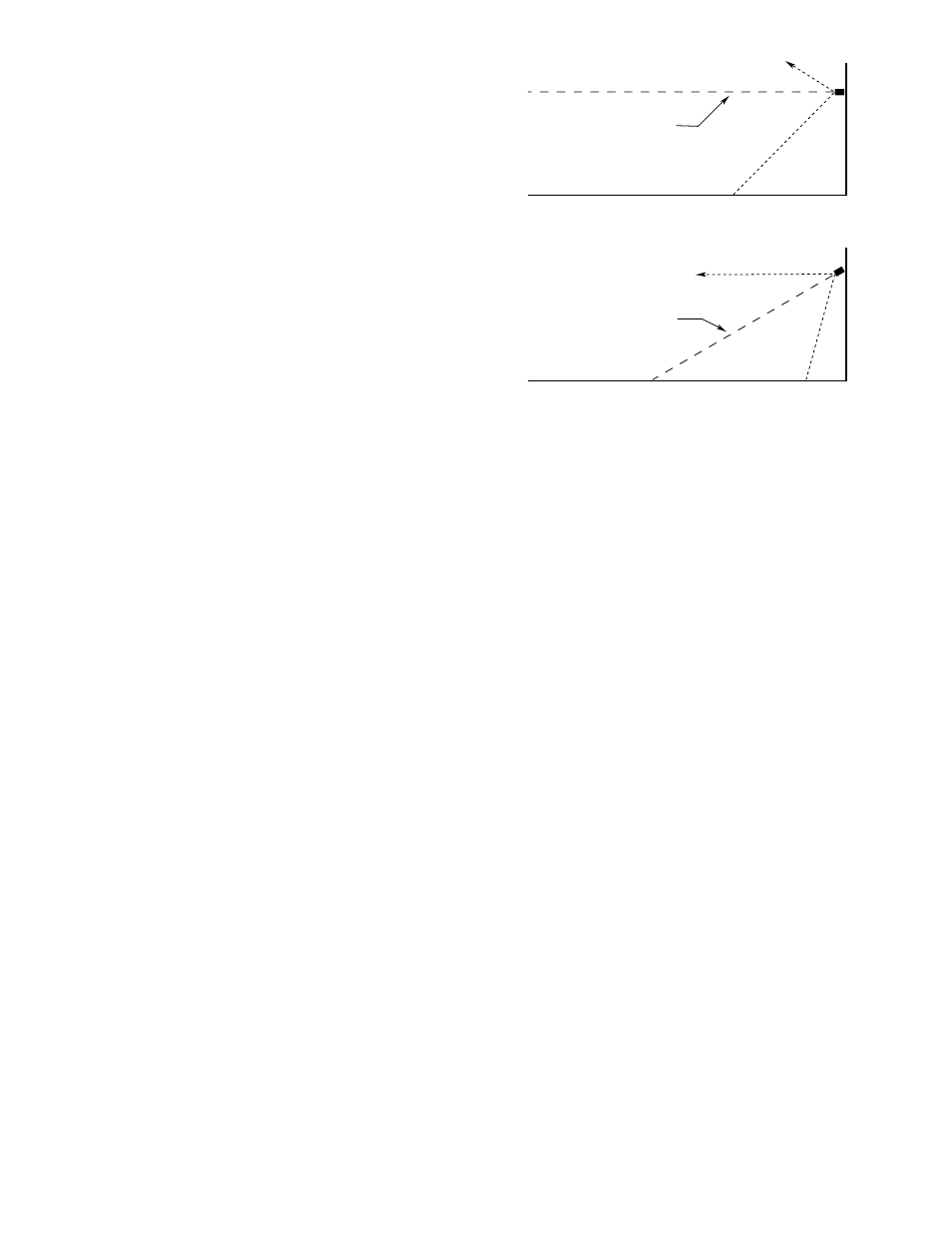
• For outdoor applications, the detector should be
aimed downward at least 10 to 20 degrees to prevent
it from scanning the horizon. This minimizes
response to distant UV sources outside the protected
area. See Figure 1.
• Dense fog, rain or ice will absorb UV radiation and
reduce the sensitivity of the detector.
• If smoke is expected before flame, it is recommended
that smoke or other detectors be used in addition to
the U7602E.
If possible, fire tests should be conducted to verify
correct detector positioning and coverage.
WIRING REQUIREMENTS
Wire Size and Type
The system should be wired using a 14 to 22 gauge (1.3
to 0.5 mm2) cable. The wire size selected should be
based on the number of detectors connected, the
supply voltage and the cable length. An input voltage
of 18 vdc minimum must be present at the detector
to ensure proper operation.
The use of shielded cable is highly recommended to
protect against interference caused by EMI and RFI.
When using cables with shields, the shield should be
insulated at the detector and connected to earth ground
only at the control panel.
In applications where the wiring cable is installed in
conduit, the conduit should not be used for wiring to
other electrical equipment.
Protection Against Moisture Damage
Conduit systems are never completely air-tight. As a
result, significant amounts of condensation can form
within the conduit system. Since moisture can have a
detrimental effect on electronic equipment, it is
important to take proper precautions during installation
to ensure that moisture will not come in contact with the
electrical connections or components of the system.
Conduit drains must be installed at water collection
points to automatically drain accumulated moisture.
Conduit breathers should be installed at upper locations
to provide ventilation and allow water vapor to escape.
At least one breather should be used with each drain.
Conduit raceways should be inclined so that water will
flow to low points for drainage and will not collect inside
enclosures or on conduit seals. If this is not possible,
install conduit drains above the seals to prevent the
collection of water or install a drain loop below the
detector with a conduit drain at the lowest point of the
loop.
Explosion-proof conduit seals should be installed within
18 inches (46 cm) of the detector. Conduit seals
prevent the passage of vapors or flames through the
conduit. Seals are recommended even if they are not
required by local wiring codes.
95-8465
CENTER AXIS
OF DETECTOR
FIELD OF VIEW
CENTER AXIS
OF DETECTOR
FIELD OF VIEW
INCORRECT
CORRECT
NOTE: DETECTOR MUST ALWAYS BE AIMED
DOWNWARD AT LEAST 10 TO 20 DEGREES.
A1974
Figure 1—Detector Orientation Relative to Horizon
3