Det-Tronics U7602E Unitized UV Flame Detector/Controller User Manual
Page 12
10
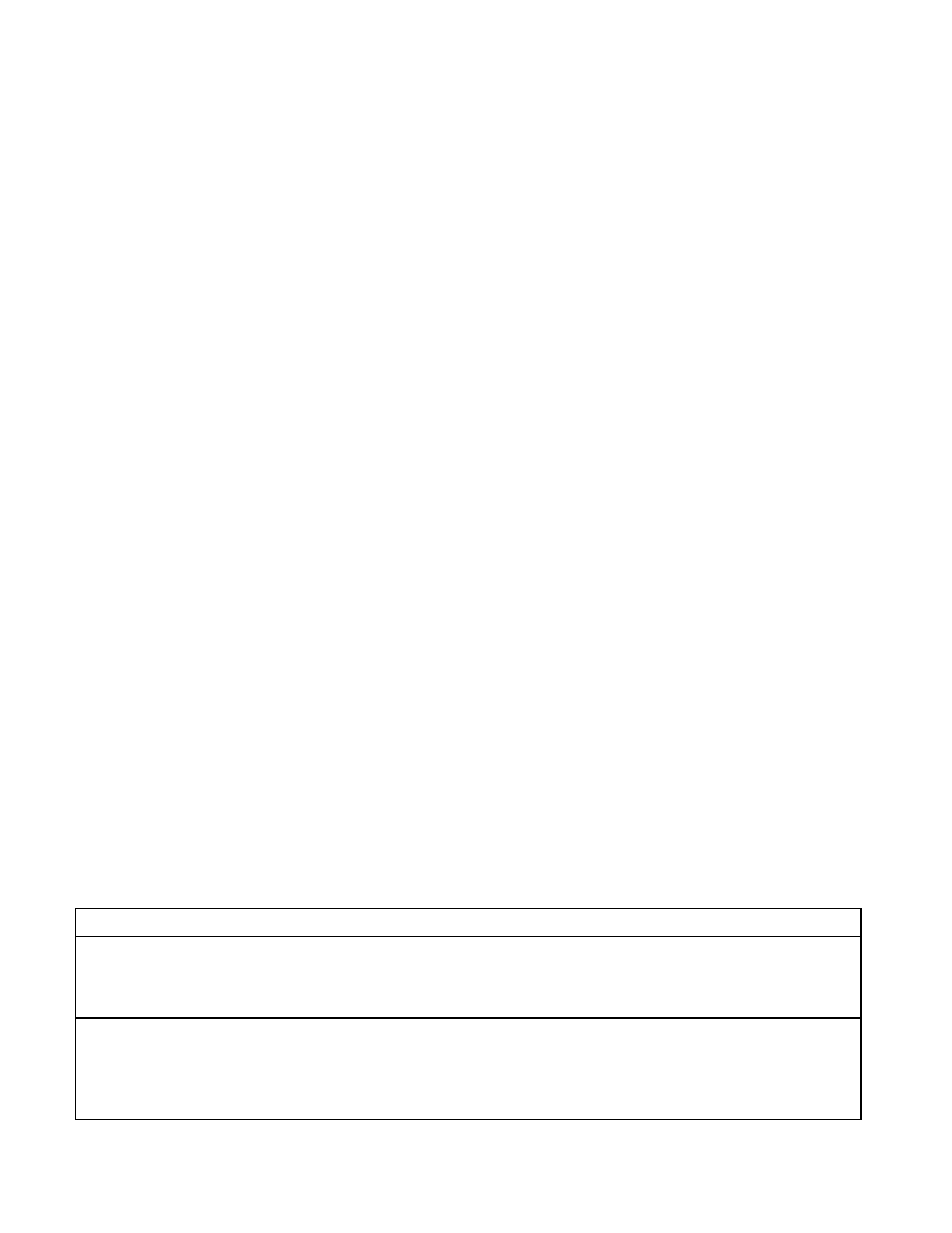
Table 4—Troubleshooting Guide
Symptom
Possible Cause
LEDs are not blinking and Fault Relay is activated (de-energized)
Dirty viewing window.
oi ring dirty, misaligned or missing.
Input voltage too low or too high.
Open, shorted or incorrect wiring.
No response to fire stimuli or to manual oi test
Dirty viewing window.
Insufficient supply voltage.
Open, shorted or incorrect wiring.
Defect in UV module.
Defect in electronic module.
5.
Hold a UV source (such as the W8066) within the
cone of vision of the detector at a distance relative
to the selected detection range or press the
oi test
button for 5 to 10 seconds (or until an alarm is
generated) — the alarm relay energizes and the
LEDs are illuminated.
Lack of response may indicate reduced sensitivity
due to contamination on the viewing window, a
damaged sensor, or electronic circuitry or wiring
problems. Refer to “Troubleshooting” for additional
information.
6.
Remove the UV source (or release the
oi test
button). If the unit is programmed for non-latching
operation, the alar m relay will become de-
energized and the LEDs will turn off when the UV
source is removed. If the unit is programmed for
latching operation, it can be reset by removing
input power (0.1 second minimum).
7.
Repeat this test for all detectors in the system.
8.
Verify that all detectors are properly aimed at the
area to be protected.
9.
Enable extinguishing equipment when the test is
complete.
FALSE ALARM TEST
1.
Disable all alarm response equipment.
2.
Allow the system to monitor the protected area for a
period of time with all the normal operations in the
area taking place. If the detector responds
(indicating a fire when no fire has occurred), check
the area to see if UV sources are present. If
possible, remove the sources, or reposition the
detector so that the sources fall outside the cone of
vision. If problems still occur, adjust the time delay,
sensitivity or arc rejection settings.
The model U7656 Hand-Held UV Monitor is
available from Detector Electronics for conveniently
scanning the protected area to verify the presence
and to identify the source of UV radiation.
3.
Recycle power and test again as described above.
4.
Once the correct settings are obtained, turn on all
alar m and extinguishing equipment that is
connected to the system. Record all switch
settings for future reference.
TROUBLESHOOTING
Table 4 is intended to serve as an aid in locating the
cause of a system malfunction. If the problem cannot
be corrected, contact the factory for assistance.
PERIODIC CHECKOUT PROCEDURE
To ensure reliable protection, the system should be
tested on a regularly scheduled basis using manual
oi, a live flame, or other UV source such as the W8066.
To test the system, perform the “Fire Alarm Test” as
described in the “Startup Procedure” section of this
manual.
MAINTENANCE
The detector requires no periodic calibration. However,
to maintain maximum sensitivity, the viewing window
must be kept clean at all times.
To clean the optical surfaces, remove the
oi ring from
the detector by gently squeezing the tabs together and
then pulling out. Clean the viewing window and the
back side of the
oi ring using a clean cloth or tissue
and Det-Tronics window cleaning solution. Avoid the
use of commercial glass cleaners, since many of them