Det-Tronics U7602E Unitized UV Flame Detector/Controller User Manual
Page 6
When using steel wire armored or mineral-insulated
copper-sheathed cable, select an approved gland with
a watertight compression stage and an overall gland
shroud for outdoor applications. A sealing washer must
be fitted between the gland and the conduit/cable entry
to ensure IP66 rating.
WIRING PROCEDURE
The following procedure should be used for mounting
and wiring the detector.
1.
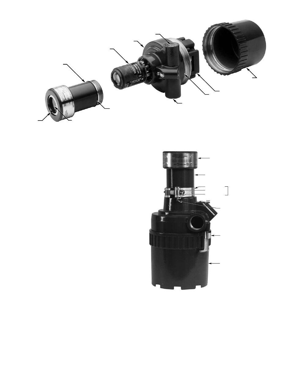
Remove the sensor housing from the bulkhead (turn
counterclockwise). Install the sensor module and
replace the sensor housing. See Figure 2.
NOTE
If the detector is equipped with a cover locking
device, it must be loosened using a hexagonal
(Allen) wrench (see Figures 3A and 3B).
2.
Mount the swivel mounting bracket using 1/4 inch
(M6) screws with a length of at least 1 inch (25
mm). The mounting surface should be free of
vibration. Allow adequate space around the swivel
to facilitate aiming and wiring of the detector.
Armored flexible conduit should be used for the
final 3 feet (one meter) of the cable run to allow for
aiming and alignment of the detector.
ELECTRONIC MODULE
REAR HOUSING
CONDUIT ENTRY
SENSOR MODULE
DETECTOR WINDOW
SENSOR HOUSING
BULKHEAD
CONDUIT ENTRY
oi RING
O-RING
O-RING
A1840
Figure 2—U7602E Detector Assembly
4
LENS CAP
BARREL
STRAP
CATCH SCREW
CATCH
COVER LOCKING ASSEMBLY
BLIND HOLE
COVER LOCKING CLAMP
REAR HOUSING
C1509
Figure 3A—Cover Locking Devices