Tronics – Det-Tronics U7602E Unitized UV Flame Detector/Controller User Manual
Page 3
NOTE
Not compliant to FM 3260 (2000).
IMPORTANT
Be sure to read and understand the entire
instruction manual before installing or operating
the flame detection system.
WARNING
Do not open the detector assembly in a
hazardous area when power is applied.
CAUTION
The wiring procedures in this manual are intended
to ensure proper functioning of the device under
normal conditions. However, because of the
many variations in wiring codes and regulations,
total compliance to these ordinances cannot be
guaranteed. Be certain that all wiring complies
with the NEC as well as all local ordinances. If in
doubt, consult a qualified official before wiring the
system. Installation must be done by a properly
trained person.
CAUTION
To prevent unwanted actuation, alarm and
extinguishing devices must be disconnected prior
to performing detection system tests.
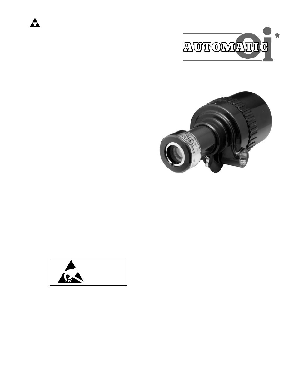
DESCRIPTION
The U7602E is a unitized ultraviolet (UV) flame detector,
containing a UV sensor module and control circuitry in
an explosion-proof enclosure. The detector is equipped
with both automatic and manual
oi test capability.
Standard outputs include fire and fault relays, and an
optional 4 to 20 ma output. Field selectable options
include latching/non-latching relays, sensitivity, time
delay and arc rejection. Operating status is indicated
by red LEDs that are visible through the detector’s
viewing window. For product certification details,
reference the Specifications Section.
DATA LOGGER
The optional data logger provides status recording
capability for the detector. Important status data such
as power-up/down, faults and alarms are date and time
stamped as they occur and stored in non-volatile
memory. Up to 510 events can be recorded — up to
63 fire alarm events and up to 447 non-fire events. This
data is later uploaded to a personal computer (PC)
where it can be displayed, saved and/or printed.
The Data Logger system consists of a special
electronic module (located inside the detector
enclosure) and a W6300 Detector Inspector™, which
provides the interface between the electronic module
and the PC.
The W6300 Detector Inspector is furnished with an RS-
232 serial port for connection to the serial port of the
PC. Communication between the data logger module
and the PC uses the Modbus RTU protocol, with the
data logger module configured as a Modbus slave.
© Detector Electronics Corporation 2003
3/03
95-8465-03
*
oi
is Detector Electronics' Trademark for its patented Optical
Integrity Systems, U.S. Patent 3,952,196, United Kingdom Patent
1,534,969, Canada Patent 1,059,598.
INSTRUCTIONS
Unitized Ultraviolet Flame Detector/Controller
U7602E
DET
-
TRONICS
®
ATTENTION
OBSERVE PRECAUTIONS
FOR HANDLING
ELECTROSTATIC
SENSITIVE DEVICES