Det-Tronics U7602E Unitized UV Flame Detector/Controller User Manual
Page 7
3.
Attach the detector to the swivel mounting bracket.
4.
Remove the rear housing from the bulkhead (turn
counterclockwise).
5.
Connect the wires to the appropriate screw
terminals on the terminal block. Refer to Figures 4
through 8.
NOTE
Connect the shield to power supply minus (circuit
ground) at the detector end. At the fire panel
end, connect the shield and power supply minus
to chassis ground through a 0.47 µF 400 Volt
non-polarized capacitor (not supplied).
6.
Install any optional accessories (such as air
shields).
7.
Set the rocker switches on the DIP switch assembly
on the electronic module. Refer to “Switch Setting
Procedure” below.
NOTE
When installing the U7602E with Apollo module,
refer to Appendix B for a wiring diagram and
switch setting information.
95-8465
5
A1841
STRAP
COVER
LOCKING
ASSEMBLY
BARREL
LENS CAP
CATCH SCREW
CATCH
BLIND HOLE
SCREW
COVER LOCKING CLAMP
USING
Figure 3B—Cover Locking Devices
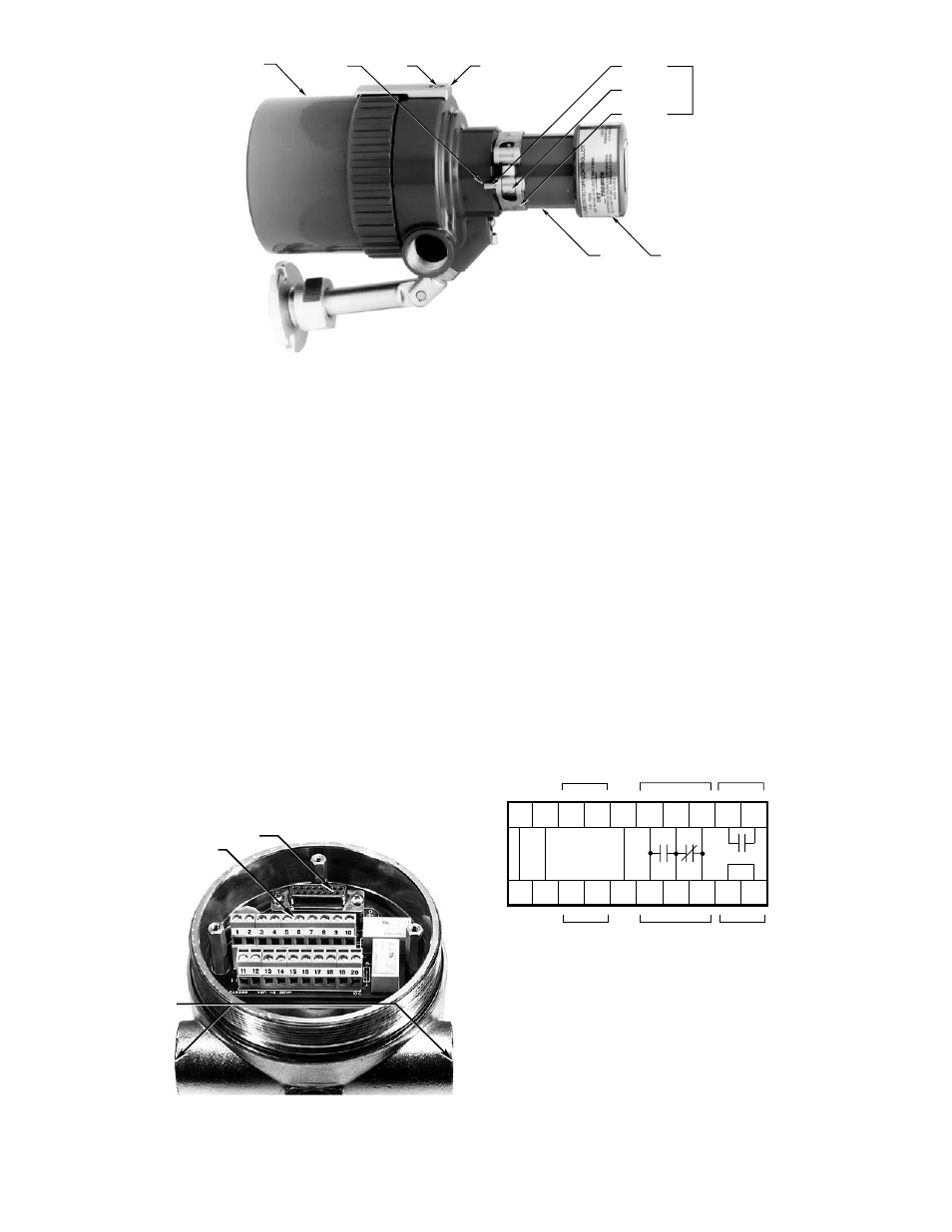
A1511
ELECTRONIC MODULE CONNECTOR
TERMINAL CONNECTIONS
CONDUIT ENTRY
Figure 4—Location of Terminal Strips Inside Bulkhead
FAULT RELAY IS
SHOWN DE-ENERGIZED,
BUT IS NORMALLY
ENERGIZED WITH
POWER APPLIED AND
NO FAULTS PRESENT.
*
FIRE
FAULT*
A1842
+
—
+
—
oi
NO C NC
+
—
+
—
oi
NO C NC NO C
FIRE
4 TO 20 MA
SPARES
REF
1 2 3 4 5 6 7 8 9 10
11 12 13 14 15 16 17 18 19 20
NOTES:
1. INPUT VOLTAGE IS 18 TO 32 VDC.
2. FOR MANUAL
oi
, CONNECT A NORMALLY OPEN SWITCH
(CAPABLE OF SWITCHING 4 MA AT 32 VDC
AND WITH RESISTANCE NO MORE THAN 25 OHMS)
BETWEEN THE NEGATIVE (–) SIDE OF THE DC POWER SOURCE
AND TERMINAL "5" OR "15" ON THE DETECTOR TERMINAL BLOCK.
EACH DETECTOR SHOULD HAVE ITS OWN
oi
TEST SWITCH.
3. RELAY CONTACTS RATED 5 AMPERES RESISTIVE AT 30 VDC.
4. CONNECT THE SHIELDS TO EARTH GROUND AT THE POWER SOURCE.
DO NOT GROUND THE SHIELD AT THE DETECTOR HOUSING
(UNLESS REQUIRED BY LOCAL CODES).
Figure 5—U7602E Terminal Configuration