Electronic module installation, Startup procedure – Det-Tronics U7602E Unitized UV Flame Detector/Controller User Manual
Page 11
95-8465
9
ELECTRONIC MODULE INSTALLATION
1.
Ensure that the switch settings on the module are
correct and that the wiring to the detector is correct.
2.
Install the electronic module, ensuring that the
connector is aligned correctly. Tighten the three
captive screws that hold the electronic module in
place. See Figures 2 and 9.
3.
Replace the rear housing and hand tighten to
ensure proper sealing.
4.
Aim the detector at the potential hazard and tighten
the swivel nut.
5.
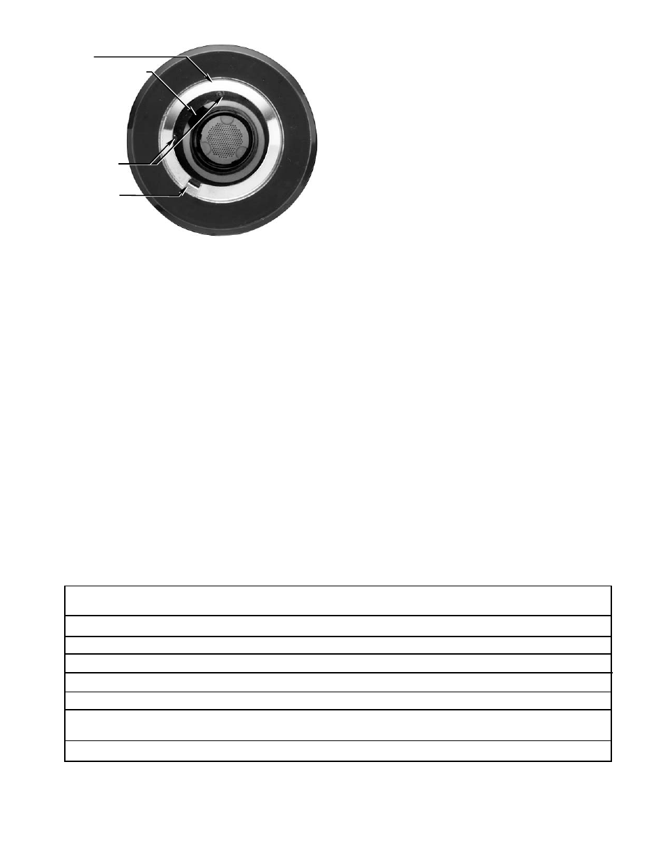
Check the viewing window surface (Figure 10) and
ensure that:
A) the
oi source (UV test lamp) is located on top
B) the split in the
oi reflective ring is not aligned
with the UV test lamp on the detector module
C) the split in the
oi ring is directed downward to
prevent a buildup of contaminants between the
oi ring and the viewing window.
6.
Clean the viewing window and
oi ring using the
procedure described in the “Maintenance” section.
STARTUP PROCEDURE
When installation of the equipment is complete, the fire
alarm and false alarm tests should be performed.
Table 3 indicates the condition of the Fire relay, Fault
relay, optional 4 to 20 ma output and LEDs for each
detector status.
FIRE ALARM TEST
1.
Disable any extinguishing equipment that is
connected to the system.
2.
Apply input power to the system. Allow a one
second power-up delay.
NOTE
The Fault Relay does not energize until after the
power-up delay is complete.
3.
Be sure that the detector viewing window and
oi ring
are clean and that the
oi ring is properly installed.
4.
Optional accessories (such as air shields) should
be installed before the test is performed.
SPLIT IN oi RING
(MUST BE POSITIONED
ON THE DOWNWARD SIDE
OF UNIT WHEN MOUNTED)
OPTIONAL LEDs
UV TEST LAMP
*
OPENING
A1843
oi RING
*
UV TEST LAMP OPENING MUST NOT BE ALIGNED WITH SPLIT IN oi RING
NOTE: oi RING NOT USED WITH INTERNAL REFLECTION MODEL.
Figure 10— Detector Viewing Window
Status
LEDs
Optional
Fire Relay
Fault Relay
4 to 20 ma Output*
Normal with automatic oi selected
Blink every 5 seconds
4 ma
De-energized
Energized
Normal with manual oi selected
Blink every 10 seconds
4 ma
De-energized
Energized
Fault (General)
Off
0 ma
De-energized
De-energized
Power Supply Fault
Off
1 ma
De-energized
De-energized
oi Fault
Off
2 ma
De-energized
De-energized
UV being detected,
LEDs continue blinking
16 ma
De-energized
Energized
but time delay not yet satisfied
Fire (relay actuated)
On
20 ma
Energized
Energized
* Fire signal always takes priority on the current loop.
Table 3—U7602E Detector Status/Indications