Description – Det-Tronics ATX10 Transmitter User Manual
Page 5
2.5
95-8657
3
ATX10 only
CuRRenT OuTpuT—
4-20 mA with HART (non-isolated, sourcing*)
20 mA indicates Alarm condition
16 mA indicates Pre-Alarm condition
4 mA indicates Normal condition
2 mA or less indicates a Fault condition.
* Isolated or sinking operation requires the use of a
FlexVu
®
Model UD10 Display.
mAXimum lOOp ReSiSTAnCe—
300 ohms at 18 Vdc; 600 ohms at 24 Vdc.
wiRing TeRminAlS—
Rated for 14 to 18 AWG (2.5 to 0.75 mm
2
) wire.
leD STATuS inDiCATORS—
Power (Green) Steady = Power on
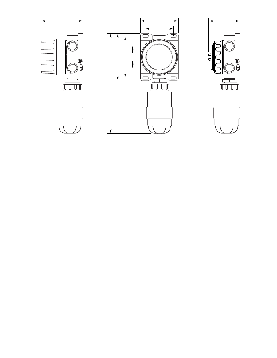
Twice per second = Manual AIC Fault (Yellow) Steady = Critical Fault Alarm (Red) Steady = Alarm Twice per second = Pre-alarm DescriptiOn The FlexSonic Acoustic Detector is comprised of two main components: the AC100 Acoustic Sensor, and the ATX10 Acoustic Transmitter. AC100 gas leaks by looking for changes in the spectrum of the received acoustic signal. To do this, the AC100 employs a high performance microphone and digital signal processing (DSP) technology to continuously monitor the acoustic signal. The wide dynamic range and spectral resolution enable the sensor to provide both superior sensitivity and false alarm discrimination. The AC100 Acoustic Sensor can be connected directly to the ATX10 Transmitter, or mounted remotely using an optional Sensor Termination Box (STB). 3.46 (8.8) 4.7 (11.9) 2.7 (6.9) 3.77 (9.6) 5.16 (13.1) 5.2 (13.2) 5.86 (14.9) 12.33 AC100 WITH ATX10 AC100 WITH ATX10 OR STB AC100 WITH STB A2610 Figure 1—Dimensions of Acoustic Detector in inches (Centimeters)
The AC100 Acoustic Sensor detects events such as
(31.3)