Det-Tronics ATX10 Transmitter User Manual
Page 18
2.5
95-8657
16
WIRING PROCEDURE
Ensure that all cables are terminated properly.
Conductor insulation should be stripped off with a bare
conductor length of 0.2 inch (5 mm) minimum and 0.7
inch (18 mm) maximum. Ensure that cable shield is
properly terminated and that bare shield wire is not
allowed to accidentally contact the metal housing or
any other wire.
impOrTanT
the AC100 GND wire (green, 16 AWG, 1.31 mm
2
)
must be properly grounded inside the StB
or AtX10 to maintain proper Intrinsic Safety
connections. A lug is provided and must be
properly crimped to the wire and secured with
the provided screw and washer at the location
marked by the GND symbol. the AC100 and the
adjoining StB/AtX10 are also provided with an
external GND connection (lug screw and washer
provided) that must be bonded to a suitable earth
GND connection. In addition, the power supply
GND must be terminated at the StB/AtX10 to
ensure 1 ohm or less resistance.
Figure 12 shows the wiring terminals on the ATX10
Transmitter.
Figure 13 shows an AC100 wired directly to an ATX10
Transmitter.
Figure 14 shows an AC100 connected to an STB
termination box and wired to an ATX10 Transmitter.
Figure 15 shows power and signal wiring for an ATX100
wired to a PLC.
Figure 16 shows an ATX10 with AC100 wired to a FlexVu
UD10 Universal Display.
See Figure 17 for benchtop test wiring.
Note
For proper HARt communication, a signal loop
resistance of 250 ohms must be present at the
4-20 mA output terminals.
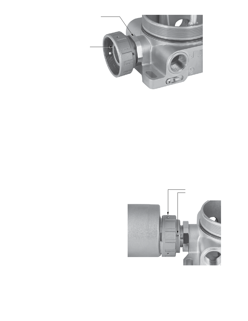
Figure 10—Connector Assembly Attached to Termination box
TIGHTEN LOCK NUT AGAINST TERMINATION BOX
TIGHTEN WITH 35MM SOCKET WRENCH
A2620
Figure 11—Set Screw locations on Connector Ring
SET SCREWS
A2621