Danger caution – COATS Pit Tire Changer User Manual
Page 16
G. On a daily basis, inspect the unit and check to be
certain that all systems are operating normally.
Detailed inspection and testing procedures are speci-
fied for various components at regular intervals. Set up
a chart and assign responsibility for these items.
Replace any damaged or missing safety
decals. They are available from COATS, (800)
688-6359.
Important: These instructions will help you service
the unit. Instructions are for a person with some
mechanical ability and training. No attempt has been
made to describe all basic steps. For example, how to
loosen or tighten fasteners. Also basic procedures
such as cycling systems and checking operation of the
equipment are not fully described since they are
known to anyone who does mechanical and service
work. Do not attempt to perform work beyond your
ability or at which you have no experience. If you need
assistance, call an authorized service center or contact
COATS directly, (800) 688-6359.
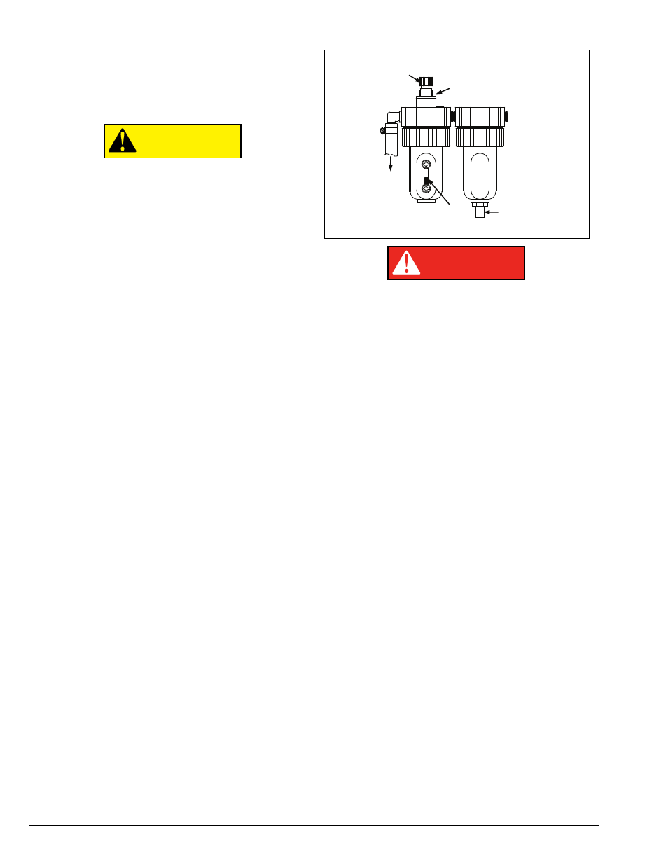
Separator/Lubricator Maintenance
Check oil and water levels regularly, and perform
these maintenance items weekly:
A. Disconnect air supply to machine.
B. The Separator (Filter) unit is equipped with an auto-
matic drain and should not normally need draining.
C. If the fluid level is greater than 1/4" from the top of
the gauge, add oil. Remove the filler plug on top of the
lubricator and add SAE 10W non-detergent oil or an air
tool oil to bring the level up to 1/4" from the top of the
gauge. Replace filler plug and clean up any spilled oil.
D. Adjust the oil flow by turning the black flow adjust-
ment knob and turning it to increase or decrease the
flow. Watch the formation of oil drops in the see-
through oil chamber. Reconnect the air supply and con-
tinually cycle the bead loosener through full strokes
and count the drips during the cycles. The delivery of
oil to the airline should be about 1 drop per 10 cylinder
cycles. Adjust flow as required.
Never inflate tire above manufacturer’s rec-
ommended pressure after bead is seated.
Any required inflation above 60 PSI should
be performed in an inflation chamber/safety
cage or securely mounted on the vehicle if
an inflation chamber is not available. A tire
explosion may cause personal injury or
death to operator or bystanders.
Air Source
This model requires a a 5 CFM air source at 150 PSI.
The operating pressure range for all models is between
125 PSI and 175 PSI at the machine.
Electrical Source
Electric models require power from a 30 amp, 120
volt electrical circuit. Have a licensed electrical techni-
cian perform any necessary changes to the power
source before plugging in the unit. The electrical source
must have a solid connection (less than 1 ohm)
between ground and building ground.
DANGER
CAUTION
12 •
Important: Always read and follow the operating instructions.
Oil Flow
Adjuster
Knob
Air Out
Reg
G
Auto Drain
Outlet
Separator
Lubricator
Oil Fill
(Behind Oil
Flow Adjuster)
Oil Level
Check
A
Regu
Adjus
Kn
Air Out