Caution, Caution danger – COATS Pit Tire Changer User Manual
Page 11
Important: Always read and follow the operating instructions.
• 7
Inflation
Tire inflation is performed in three steps: BEAD
SEAL, BEAD SEAT, and INFLATION. These steps are
explained in detail on page 14. Read the explanation of
each step and understand them thoroughly before pro-
ceeding.
Tire failure under pressure is hazardous.
This tire changer Will Not Restrain
Exploding Tires, rims or other related equip-
ment. Inspect tire and wheel carefully for
match, wear, damage, or defects before
mounting. Always use approved tire bead
lubricant during mounting and inflation.
The clip-on chuck allows the operator to
keep hands and entire body back from
inflating tire. The chuck must be an
open/freeflow style with all parts in proper
working order.
Check for proper inflation gauge operation.
Accurate pressure readings are important to
safe tire inflation. Refer to the Operating
Maintenance section of this manual for
instructions.
The inflation pedals, located at the rear of the right
side of the machine, controls the flow of air through
the inflation hose, and has three positions.
Note: The clip-on chuck on the end of the hose should
always be an open/freeflow style with all parts in
proper working order.
Position 1 - Tire Pressure – With the inflation hose
attached to the tire valve and the pedal in this position,
the air gauge will register the air pressure in the tire.
Whenever your foot is removed from the pedal, it will
return to this position.
Position 2 - Tire Inflation – This is the DOWN acti-
vated position. With the inflation hose attached to the
tire valve and the pedal in this position, line pressure is
allowed to flow through the valve system and into the
tire for inflation. Correct tire pressure is not indicated
on the gauge in this position.
Position 3 - Pressure Bleed – This is the UP activated
position. With the inflation hose attached to the tire
valve and the pedal in this position, tire pressure can
be bleed from the tire.
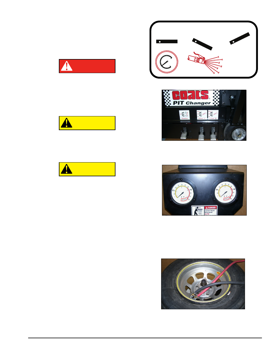
Note the Inflation Pedal Positions (See Diagram)
Inflation Foot Pedals (two on right)
Note that this machine has two inflation circuits. One
for the tire and one for the liner.
Inflation Gauges
Note: Actual gauge face may vary depending on
model.
Note that there are two gauges. The front (left) gauge
is connected into the “A” inflation circuit. The rear
(right) gauge is connected to the “B” inflation circuit.
Twin Air Circuits
Clip-on air chucks attached to rim valves for tire and
liner inflation or bleed.
CAUTION
CAUTION
DANGER
Bleed
Pressure
From
Tire
POS 1
POS 2
POS 3