COATS 5040 A/E Tire Changer User Manual
Page 9
Important: Always read and follow operating instructions.
• 5
5.
Determine the mounting side of the wheel. The
mounting side is the narrow side of the drop center.
(Tire removed in Figure 4 for clarity.)
Figure 4 - Determining Mounting Side of Wheel
6.
Place tire/wheel assembly on table top with mount-
ing side up (Figure 5). Use the clamp control pedal to
move the clamps inwards (push pedal down) or out-
wards (toggle pedal up). Clamp steel wheels from the
inside (clamps push outwards against wheel). Clamp
mag and custom wheels from the outside (clamps push
inwards against the outside rim edge). Place rim flange
into rear clamp and slowly move the other clamps
inward until they contact the rim. Observe closely to
prevent tire/wheel damage.
Figure 5 - Place Tire/Wheel Assembly on Table Top
7.
Move the swing arm into position. Pull the locking
handle forward to release the slide. Push down on the
top of the vertical slide to move the demount tool into
contact with the rim edge. Push the locking handle
back to lock the slide into place. As the slide is locked,
the mount/demount tool
will move upward approxi-
mately 1/8 inch from the
rim edge.
Note: On plastic mount/
demount tool, the upward
movement should be
limited to 1/16-inch maxi-
mum.
Figure 6 - Position Mount/
Demount Tool
8.
The mount/demount tool roller should be in contact
with the rim edge. Turn the swing arm adjusting knob
to move the tool away from the rim 1/8 to 1/4 inch.
On expensive and polished rims, it is recommended a
plastic bootie (p/n 8183373) be used over the mount/
demount tool roller.
Figure 7 - Adjust Swing Arm to Position Tool Roller
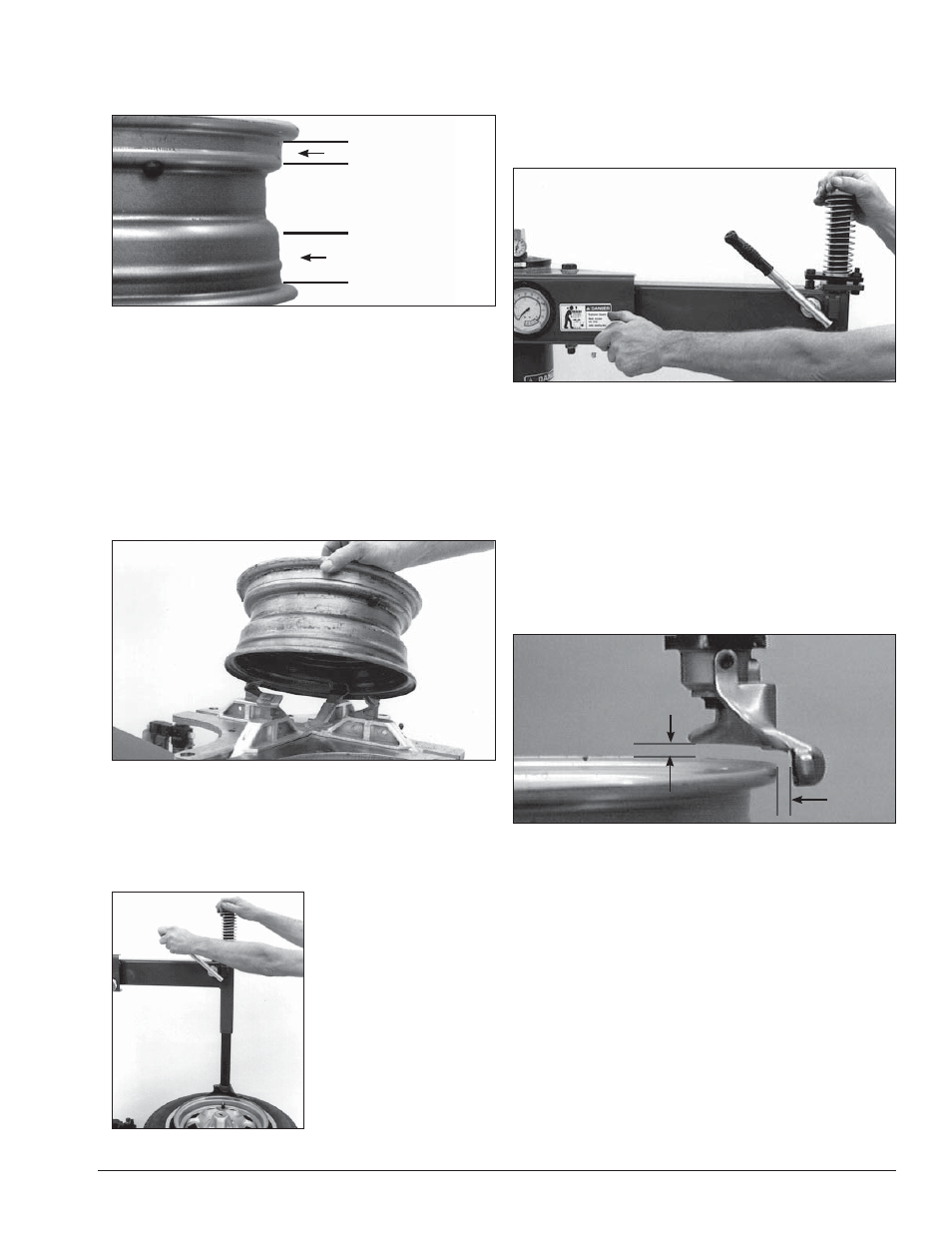
9.
Check tool positioning. Mount/demount tool should
be positioned with 1/8 to 3/16” clearance between the
top of the rim edge and the bottom of the tool (with
plastic mount/demount tool it is recommended the ver-
tical clearance be limited to a maximum of 1/16-inch),
and 1/8 to 1/4 inch clearance between the rim edge and
the tool. This clearance will be maintained as long as the
locking handle and adjustment knob are not changed.
The operator may swing the arm out of the way and
back into place again without needing to reposition the
tool (when changing a set of the same wheels).
Figure 8 - Proper Mount/Demount Tool Position
IMPORTANT: The vertical tool clearance may change
with machine use and should be inspected often.
Failure to maintain the proper clearance may result in
damage to the wheel rim and/or tire.
Narrow Side
Drop Center
Long Side
1/8" to 3/16"
1/8" to 1/4"