Warning, Danger, Caution – COATS 5040 A/E Tire Changer User Manual
Page 13: Infl ation
Important: Always read and follow operating instructions.
• 9
Infl ation
Tire inflation is performed in three steps: BEAD
SEAL, BEAD SEAT, and INFLATION. These steps are
explained in detail. Read the explanation of each step
and understand them thoroughly before proceeding.
DANGER
Tire failure under pressure is hazardous.
This tire changer Will Not Restrain Explod-
ing Tires, rims or other related equipment.
Inspect tire and wheel carefully for match,
wear, damage, or defects before mounting.
Always use approved tire bead lubricant
during mounting and inflation.
WARNING
The clip-on chuck allows the operator to
keep hands and entire body back from inflat-
ing tire. Improper use of the clip-on chuck
could result in personal injury. The chuck
must be an open/freeflow style with all
parts in proper working order.
CAUTION
Check for proper inflation gauge operation.
Accurate pressure readings are important
to safe tire inflation. Refer to the Operat-
ing Maintenance section of this manual for
instructions.
The inflation pedal, located at the center of the left
side of the machine, controls the flow of air through the
inflation hose, and has three positions.
Note: The clip-on chuck on the end of the hose should
always be an open/freeflow style with all parts in proper
working order.
Position 1 - Tire Pressure – With the inflation hose
attached to the tire valve and the pedal in this position,
the air gauge will register the air pressure in the tire.
Whenever your foot is removed from the pedal, it will
return to this position.
Position 2 - Tire Inflation – This is the first activated
position. With the inflation hose attached to the tire
valve and the pedal in this position, line pressure is
allowed to flow through the valve system and into the
tire for inflation. Correct tire pressure is not indicated on
the gauge in this position.
Position 3 - Bead Sealing – This is the second and
last activated position. With the inflation hose attached
to the tire valve and the pedal in this position, line pres-
sure is allowed to flow through the valve and to the
air-flate bead seal jets on the tabletop for bead sealing.
1.
If the rim has been clamped from the outside for
tire mounting, release the clamps, lift the tire, and move
the clamps to the center of the tabletop.
The inflation pedal, located at the center of the left
side of the machine, controls the flow of air through the
inflation hose.
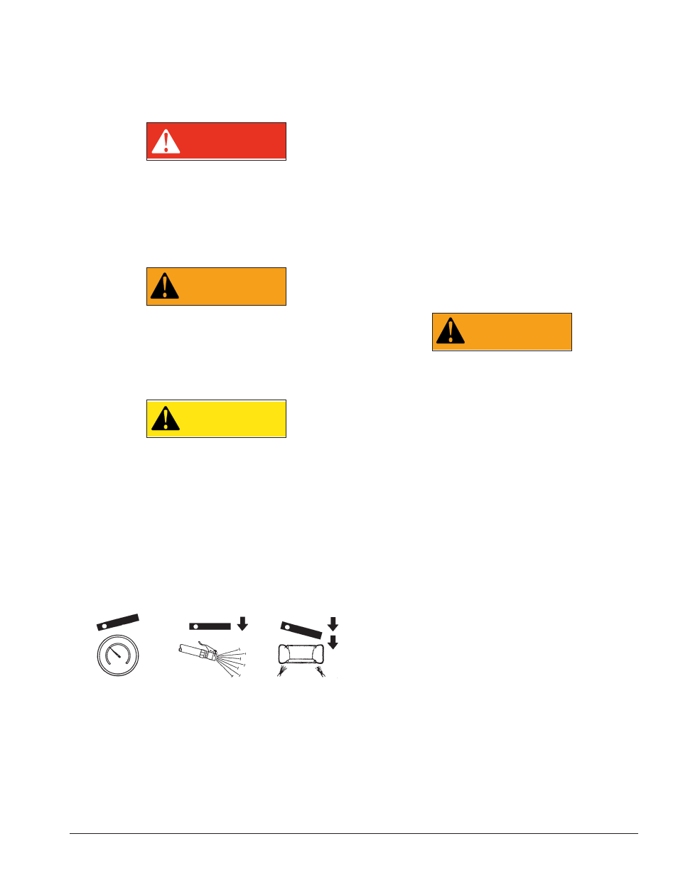
Note the Pedal Positions (See Diagram)
WARNING
Use of bead sealing jets without a tire in
place can cause dirt and debris to be blown
into the air with enough force to injure
operator and/or bystander. Do not use the
bead sealing control position to inflate a tire.
R. This unit is equipped with a pressure limiter to
assist the operator with proper tire inflation. When the
inflation pedal is held in position 2, the pressure limiter
cycles the machine between position 2 (inflation) and
position 1 (at rest, no airflow to tire). This cycling helps
to prevent over inflation of the tire. Tires can still be
over inflated and explode with the use of this pressure
limiter if all of the instructions in this manual are not
followed completely. The pressure limiter will keep
most car and light truck tires from inflating beyond 60
PSI (smaller tires may reach higher pressures). It is
the operator’s responsibility to follow all instructions
and to control inflation pressure as specified in these
instructions. Check the function of the pressure limiter
regularly and maintain it according to the instructions
provided in this manual for safe and proper operation.
Do not tamper with or attempt to adjust the pressure
limiter. Tires requiring inflation beyond 60 PSI should be
inflated in a safety cage.
Tire
Pressure
Tire
Inflation
Bead
Sealing
Inflation Pedal Positions