Robo-arm – COATS Kit 8184177 Robo-Arm and Accessory Kits User Manual
Page 4
Robo-Arm™
4 • COATS Robo-Arm™ Assembly
always loosen the top bead with the valve stem at the 2 o’clock
position first, then loosen the bottom bead with the valve stem
at the 2 o’clock position, and then continue to loosen the
remaining circumference of the beads as necessary. Avoid
loosening at 180 deg. (opposite) the valve.
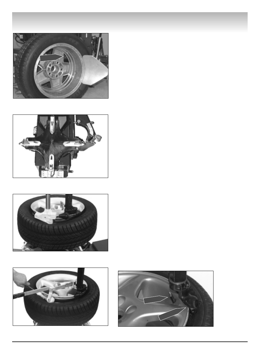
3. Loosen bottom bead, starting with valve stem at 2 o’clock
position next to the loosener shoe (Figure 5).
Aluminum and Custom Wheels
Follow instructions provided for standard steel wheels,
except:
AC. After loosening and lubricating both beads, rotate the
table top until the clamps are in the 12, 3, 6, and 9 o'clock posi-
tions (Figure 6).
AD. Clamp wheel from the outside. Position rim edge into
clamp at 12 o'clock position. Lower the wheel and depress the
clamp control pedal. Slowly move the clamps inward until they
securely contact the outside edge of the rim.
Tip: This is usually accomplished by crouching down in front
of the tire changer, holding the wheel with the right hand, and
operating the clamp control pedal with the left hand. This
allows the operator to watch the clamps as they move to
ensure proper, damage-free clamping.
4. Clamp the wheel to the table top. Always clamp custom
wheels from the outside.
5. Depress the tire sidewall downward with the aid of the
helper foot providing clearance for the mount/de-mount head
to be positioned (Figure 7). Move swing arm into place.
Increase the horizontal distance between the demount head
and the wheel an additional 1/16 to 1/8 inch with the adjust-
ment knob.
6. Lubricate upper bead liberally. Use the bead roller tool to
help push the tire bead down so bead area is easier to reach for
lubrication (Figure 8).
7. Locate the valve stem just before the demount head
before proceeding (Figure 9).
Valve Stem
Figure 5 - Loosen Bottom Bead
Figure 6 - Rotate Table Top to 12 O’clock
Figure 7 - Helper Foot Depressing Sidewall of Tire
Figure 8 - Lubricate Upper Bead
Demount Head
Valve Stem
Figure 9 - Position Valve Stem Under Demount Head