Calibration – COATS 1250 Series Balancer User Manual
Page 23
Important: Always read and follow the information box instructions.
• 17
Calibration
Machine Calibration
Important: Be sure to use the correct calibration
weight amount: a 4-ounce calibration weight in ounce
mode or a 100-gram calibration weight in gram mode
Important: Starting with software revision 2.0.1.9,
the factory default is set for a 4-ounce calibration
weight amount for both the ounce and the gram
weight measurement modes. Therefore, for Machine
Calibration, only the 4-ounce calibration weight is nec-
essary regardless of the weight measurement mode
setting.
To use a 100-gram calibration weight amount, when
first prompted to use the 4-ounce weight in calibration
mode, press the gram/oz key (SHIFT 9) to toggle from
4.00 to 100. Once set, the balancer retains this new
default preference in memory.
Important: Starting with software revision 2.0.1.6,
the user is only required to enter the D dimension.
Note that prior software versions still require that the
user enter all the DIMS (A, W, and D wheel dimen-
sions).
1. Mount a 16-inch steel tire/wheel assembly on the
balancer. A balanced tire/wheel is required.
Note: Position wheel so that no weights are on either
flange at the top-dead-center location. Turn the
machine OFF then ON.
2. Press and hold the SHIFT key and press 1 to select
the CAL MACHINE mode.
3. Enter the D dimension.
4. Lower the hood and press START.
5. After spin, raise the hood. Rotate wheel until the
outboard center bar blinks; attach calibration weight to
the outside flange at top-dead-center.
Figure 20 - Calibration Weight On Outside Flange At Top-
Dead-Center
6. Lower the hood and press START.
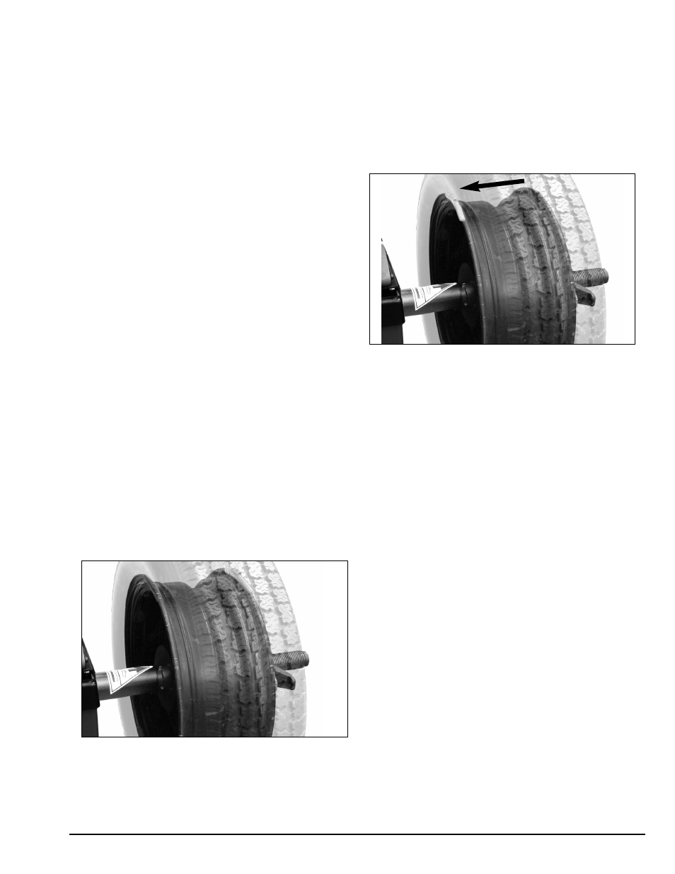
Important: It is critical that the inner weight be
placed accurately to achieve proper calibration. If the
calibration weight is not moved from the outside
flange directly across to the inside flange, an inner
weight placement error will occur. To correct, follow
the information box instructions.
7. After spin, raise the hood. Rotate wheel until the
inboard center bar blinks; move and attach the calibra-
tion weight to the inside flange at top-dead-center.
Figure 21 - Calibration Weight Moved (Directly Across) To
Inside Flange
8. Lower the hood and press START.
9. Calibration complete. Press NEXT.
Arm Calibration
Important: Always perform the Arm Calibration
immediately after Machine Calibration. The balancer
software will not permit it otherwise.
During Machine Calibration, the balancer software
calculates both the A and W dimensions. The Arm
Calibration gives the balancer software a reference
point to the edge of the faceplate and home position.
When the user enters the A dimension from the arm
rod, it calculates the difference from the machine cali-
bration A and uses that as a factor for the manual A
entry. Arm calibration also gives the D dimension a ref-
erence point from home position.
Note: Starting with software revision 3.0.0.0, CdE
will not appear in the INBOARD weight display and the
user is no longer required to enter the Code 96. Note
that prior software versions still require that the user
enter the Code 96 at the CdE prompt to access the
Arm Calibration mode.
1. Complete the Machine Calibration procedure (see
page 17).
2. Press and hold the SHIFT key and press 3 to select
the CAL ARM mode.