Warning – COATS 1250 Series Balancer User Manual
Page 19
Begin by following the Laser Guided Operation™
pro-
cedure, steps 1 through 4 on page 6.
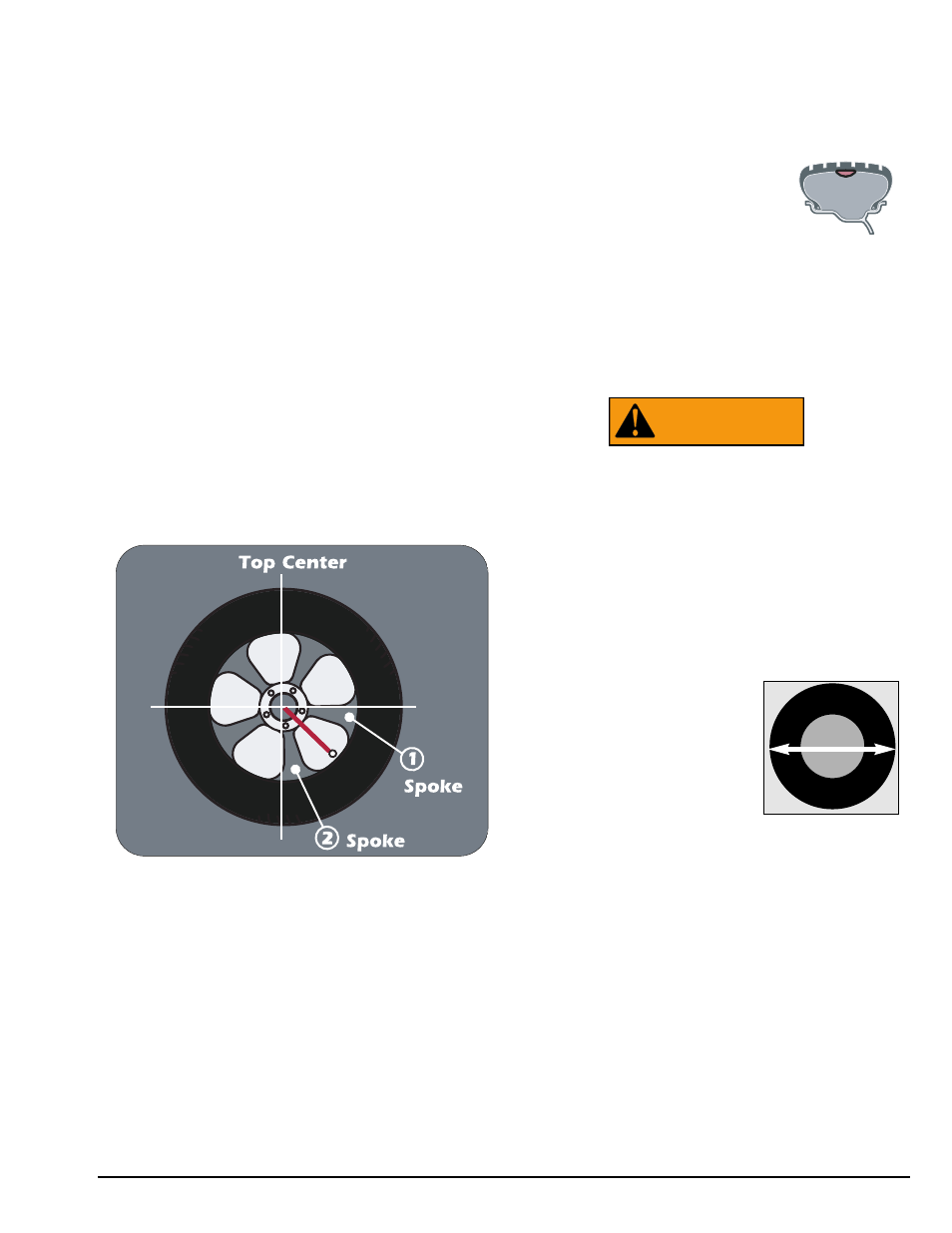
1. When unbalance is displayed, rotate wheel until
inboard center bar blinks. Attach inboard corrective
weight at top-dead-center.
2. Next, rotate wheel until the outboard center bar
blinks and the two bars on either side blink.
Note: The laser locator dot will stop blinking.
3. Select the BEHIND SPOKE mode option.
Important: Be sure that the Spoke 1 and Spoke 2
locations are on either side of the original outboard cor-
rective weight location, as shown in figure 15.
4. Rotate the wheel toward front so the laser locator
dot is behind the first spoke; press SPOKE 1 (indicator
illuminates).
5. Rotate the wheel toward rear so the laser locator
dot is behind the second spoke; press SPOKE 2 (indi-
cator illuminates). Now at the spoke 2 location, the
outboard center bar stops blinking and the two bars on
either side blink.
Note: The laser locator dot will stop blinking.
Figure 15 - Spoke 1 And Spoke 2 Locations On Either Side
Of Original Outboard Weight Location
6. Center and attach the spoke 2 outboard corrective
weight at the laser locator dot location (see figure 11
page 6).
7. Next, rotate the wheel toward the spoke 1 loca-
tion until the outboard center bar stops blinking and
the two bars on either side blink.
Note: The laser locator dot will stop blinking.
8. Center and attach the spoke 1 outboard corrective
weight at the laser locator dot location (see figure 11
page 6).
9. Respin tire/wheel to check balance.
Patch Weight Balance - Use a static patch weight bal-
ance when there is a very large unbalance in a tire
assembly or if a very large tire has a large unbalance. A
weighted balance pad (patch weight) is placed inside
the tire in the center to compensate for the large unbal-
ance.
Direct Select Weight position Patch
Static (weight location illuminates). At
this location place the corrective weight
amount at top-dead-center.
Have the following items handy: measuring tape and
various patch weight sizes.
Note: Before proceeding with Patch Weight Balance,
it is recommended that you use the Match Balance
(Optimization) procedure first, see page 16, in order to
use the smallest patch weight.
The Patch Weight Balance involves the loos-
ening of tire beads and the inflation of a
tire. Training is necessary in tire changer
operation and understanding the dangers
involved during bead seating and tire infla-
tion before attempting this stage of the
Patch Weight Balance procedure. Read the
operators manual supplied with the tire
changer and consult a supervisor.
The patch weight balance steps are as follows:
1. Direct Select Weight position PATCH STATIC. The
balancer automatically sets itself
for a STATIC balance.
2. Measure the outside tire
diameter, see figure 16, and enter
this diameter manually using the
keypad.
Figure 16 - Measure Outside Tire Diameter
3. Spin the wheel.
4. Rotate the wheel until the center weight position
bar blinks. Next, mark the tire and rim at 12 o’ clock.
Then remove the wheel assembly from the machine.
5. Disassemble the tire and rim. Place patch weight
in the tire at location marked on the tire. Reassemble
tire and rim matching the marks on the tire and rim.
6. Complete by balancing the wheel assembly fol-
lowing normal procedures.
WARNING
Important: Always read and follow the information box instructions.
• 13
Outside
Diameter