CiDRA GVF-100 Gas Volume Fraction Monitoring System User Manual
Page 80
Copyright © 2006 CiDRA Corporation
Page 10-6
20639-01 Rev 03
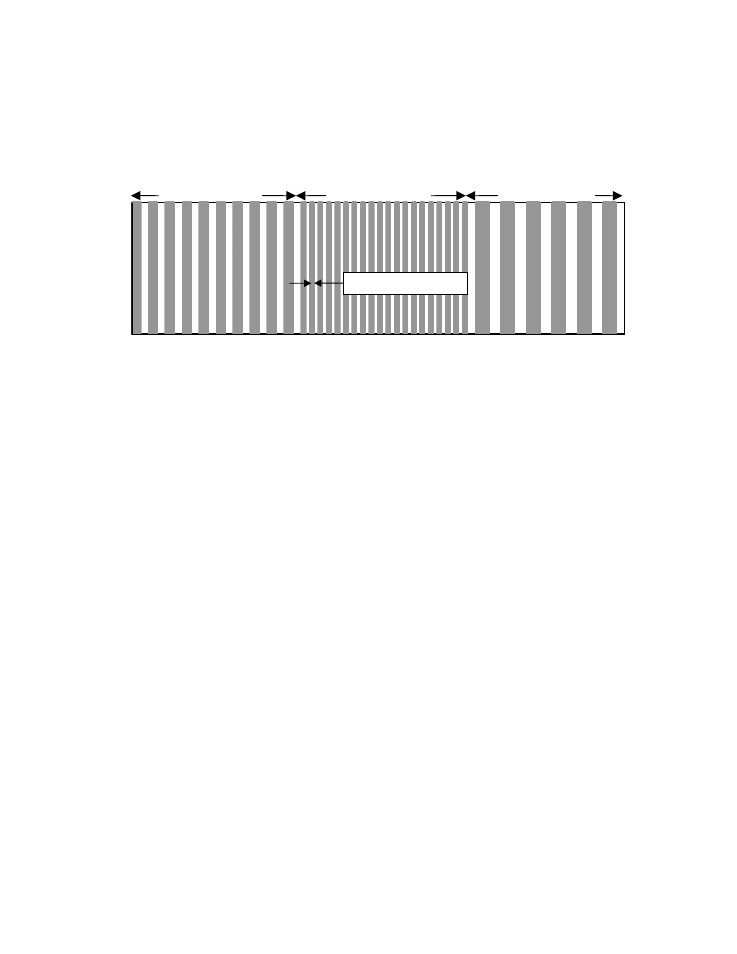
‘SOS’ and ‘GVF’ generate a pulse frequency based on the current
measurement. The pulse width will vary in order to maintain a 50%
duty cycle pulse train.
Figure 60
Speed Of Sound and Gas Volume Fraction Pulse Output
The following is an example of Pulse settings applied to Gas Volume
Fraction:
Pulse Output: GVF
Multiplier: 1
Pulse Width: 1 ms
Low cutoff: 0.000%
Min Pulses: 0 Pulses per second
Max Pulses: 100 Pulses per second
In the above example, the Pulse output frequency will vary between 0
and 100PPS (Hz), based on the actual GVF reading.
•
Alarm
The transmitter alarm is a tri-state output. The Alarm modes are ‘Off’
(no alarm conditions present) indicated by the transmitter mounted
LED off and no signal being sent to the DCS, ‘Warning’ (an alarm
condition has entered a range of condition(s) where the integrity of
readings may be suspect) indicated by the transmitter mounted LED
and alarm output relay blinking, and ‘Critical’ (an alarm condition in
which the output of the meter can no longer be considered valid)
indicated by the alarm LED on the transmitter being constantly on and
constant relay closure output to the DCS. The measurement result
should be discarded and closed loop controls switched to manual
during a critical alarm.
The alarm can be cancelled either manually or will clear automatically
when the alarm condition is no longer present depending on the menu
option selected (see below).
SOS
Time (sec)
500 fps / 100 = 5 Hz
1000 fps / 100 = 10 Hz
300 fps / 100 = 3 Hz
Multiplier = 100
0
2
4
6
Pulse Width Varies