5 sensor band installation, 5 sensor band installation -4, Figure 6 sensor band screw and alignment pins -4 – CiDRA GVF-100 Gas Volume Fraction Monitoring System User Manual
Page 21
Copyright © 2006 CiDRA Corporation
Page 7-4
20639-01 Rev 03
7.5 Sensor
Band
Installation
It will be helpful to have a second person available to assist with
holding the sensor assembly in position during installation.
Note:
Prior to installing the sensor band, remove and save the plastic
bag from the sensor band that contains two sensor calibration factor
labels. These will be used as described later in this manual for input
to the transmitter. Ensure there is no dirt or other foreign material on
the sensor assembly. Remove dirt or foreign matter using a clean
cloth dampened with water.
If the sensor band was shipped with a sensor band shorting plug
installed on the sensor band to preamplifier cable connector, ensure
the sensor band shorting plug is installed on the sensor band cable
prior to installing sensor band. Sensor bands with an “R” in the Part
Number suffix (e.g. Part #: 20686-26-R) do not require a shorting plug.
Position the SONARtrac
TM
sensor band assembly on the pipe with the
polyimide film (amber colored) against the pipe surface. If possible,
orient the flow direction arrow on the sensor assembly with the
direction of flow within the pipe. Note: If this is not possible due to
installation constraints, e.g. access to sensor fasteners, install
opposite to flow direction.
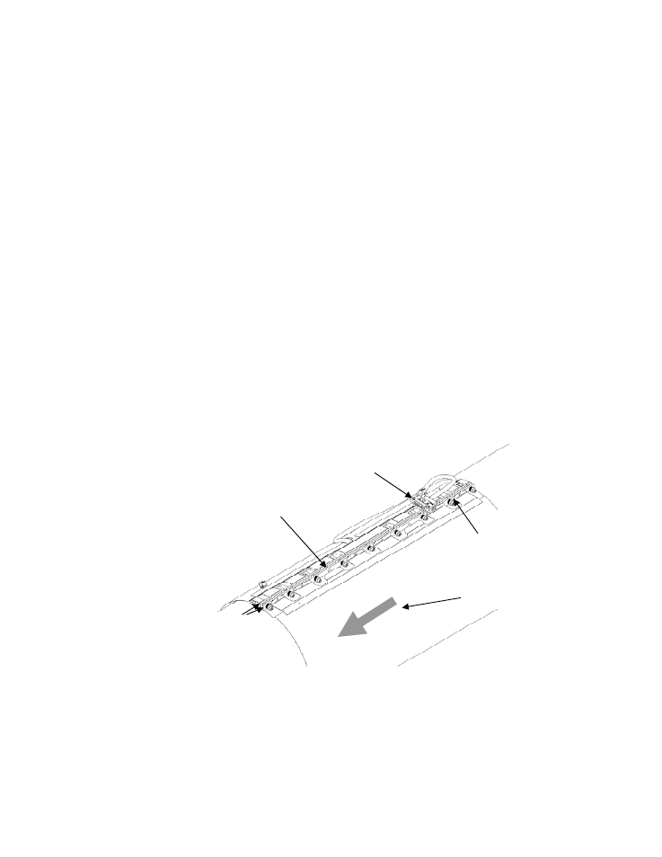
Figure 6
Sensor Band Screw and Alignment Pins
Sensor attachment screw
assembly (typical 9 places)
Alignment pins
(typical 2 places)
Flow direction arrow
Attachment rails
Sensor band shorting plug