Online manual not for resale purposes – BLITZ Toyota Celica Compressor System User Manual
Page 31
WARNING: All images and text in this manual is the property of Blitz Co., Ltd. (Japan). No parts of this manual may be
reproduced, stored in retrieval systems, or transmitted in any way without prior written permission of Blitz Co., Ltd. (Japan)
Genuin
e
Com
puter
Red wire
(thick)
Ground wire.
With 6mm
Red wire (thin)
Ignition ON
Back wire (thin)
Ground wire to the engine
computer.
Yellow wire.
To the engine computer
A wire.
(C. 58) Clutch
Blue wire (thin)
To the relay.
Blue wire (thin)
To the switch.
To the positive
battery
terminal
With 8mm
round
i
l
(C. 59) Relay
Fuse
Coupler
Coupler
Wiring Diagram
Compressor’s
Magnetic clutch
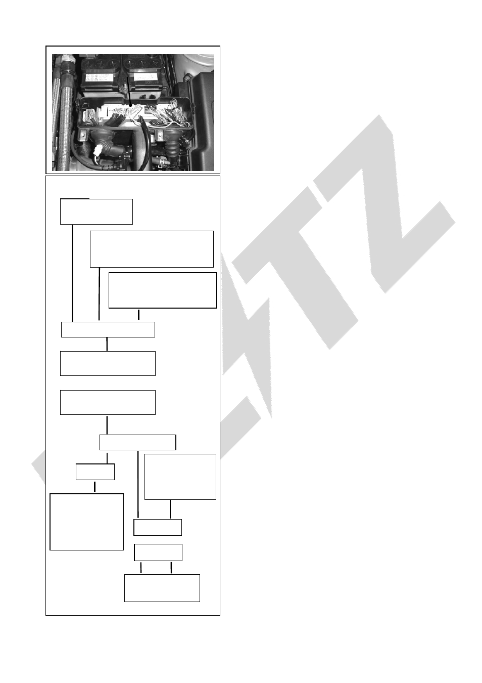
(31) Installation of the (C.63) Access computer.
①
Remove the lid from the computer box in the
engine room.
②
Disconnect the computer’s connectors.
③
Remove the genuine computer from the
computer box by removing the bolt holding the
computer stay.
④
Install the (C.61) female wire connector to the
white wire from the access computer.
⑤
Remove the stay from the genuine computer
and install it to the access computer.
⑥
Install the access computer with the steps
opposite from removing the genuine computer.
(32) Installation of the (C. 58) Clutch switch.
①
Install the (C.59) relay harness’s relay box at the
location shown in the figure. (See next page)
②
Install the (C.58) clutch switch box using a
two-sided tape. (See next page)
③
Connect the harness coupler from the
compressor to the (C. 59) relay harness coupler.
④
Connect the re wire from the (C.59) relay harness
coupler (6mm round terminal) to the ground
shown in the figure. (See next page)
⑤
Connect the red wire from the (C.59) relay box
(8mm round terminal) to the positive terminal of
the battery.
⑥
Connect the blue wire from the (C.59) relay box to
the blue wire at the (C.58) clutch switch.
⑦
Connect the (C.58) clutch switch yellow wire to
the white wire from the (C.63) access computer.
⑧
Connect the black wire from the (C.58) clutch
switch to the ground line of the computer (brown
wire) using an electro tap.
⑨
Connect the red wire from the (C.58) clutch
switch to the ignition line of the computer (black
and orange wire) using an electro tap.
※
Be careful not to damage the wires while using
the electro tap.
Online Manual Not For Resale Purposes
Online Manual Not For Resale Purposes
Online Manual Not For Resale Purposes
Online Manual Not For Resale Purposes
Online Manual Not For Resale Purposes
Online Manual Not For Resale Purposes
Online Manual Not For Resale Purposes
Online Manual Not For Resale Purposes
Online Manual Not For Resale Purposes
Online Manual Not For Resale Purposes
Online Manual Not For Resale Purposes
Online Manual Not For Resale Purposes
Online Manual Not For Resale Purposes
Online Manual Not For Resale Purposes
Online Manual Not For Resale Purposes
Online Manual Not For Resale Purposes
Online Manual Not For Resale Purposes
Online Manual Not For Resale Purposes
Online Manual Not For Resale Purposes
Online Manual Not For Resale Purposes
Online Manual Not For Resale Purposes
Online Manual Not For Resale Purposes
Online Manual Not For Resale Purposes
Online Manual Not For Resale Purposes