Install coupler handle, Install coupler – B&W Trailer Hitches RVK3600 User Manual
Page 4
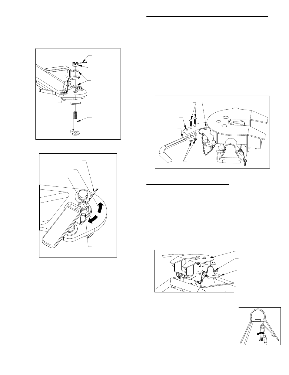
Adjust the resting angle of your
coupler plate by rotating the spring
on the driver side pivot arm. Pulling
the top of the spring away from the
cab will increase the angle of the
coupler plate. Set the angle of the
coupler so that head will tilt away
from the cab when coupling, see
figure E2. Tighten the 1/4" nut once
the spring’s orientation is set.
2.
INSTALL COUPLER HANDLE
Locate the two 3/8" x 1−1/4" button head cap screws
and the two 3/8" flanged lock nuts provided in a bolt
bag. Pull out the coupler arm and pin it with the
safety locking pin near the base of the arm as shown
in figure D1.
1.
CAUTION: Pulling the arm out away from the coupler
creates a pinch point. Use caution when installing the
handle to avoid injury.
Using the button cap screws and the lock nuts attach
the coupler handle to the arm and tighten, see figure
D1. Pull out the coupler cam handle safety pin.
2.
INSTALL COUPLER
Lubricate the polyurethane bushings on top of the
pivot arms with high grade lithium grease (available
at your local hardware/automotive store). Place the
coupler over the pivot arms. (The saddle handles
should be parallel with the base in the latched
position.) Place the saddle lock pins through the
saddle, then insert the hairpins through the holes in
the end of the saddle lock pins to secure the coupler
to the pivot arms, see figure E1.
1.
Trial and error will have to be used to find the correct
latch tension for each attachment point. After the
tension is set, replace the cotter pin and re−bend the
ends. You may have to rotate the castle nut slightly to
allow the cotter pin to pass through.
To tighten the latch handle (handle rotates without
any resistance) rotate the castle nut clockwise
(tighten) with a 15/16" wrench or socket.
Adjust the tension in the latch handle,
for parts list
and visual guide refer to figures C3 and C4.
With a pair of needle nose pliers, un−bend and remove
the cotter pin installed at the top of the latch cam.
Next adjust the height of the castle nut.
To loosen the latch handle (handle is difficult to
rotate or cannot be closed) rotate the castle nut
counter−clockwise (loosen) with a 15/16" wrench or
socket.
FIGURE D1: View looking down at side of coupler head.
FIGURE E2: Cutaway
view of driver side
pivot arm and saddle.
FIGURE E1: Coupler installed on base.
FIGURE C3: List of latch parts.
FIGURE C4: View of base leg.
3/8" LOCKING
FLANGE NUTS
COUPLER
ARM
COUPLER CAM
HANDLE SAFETY PIN
COUPLER
HANDLE
3/8" BUTTON HEAD
CAP SCREWS
SADDLE HANDLES
(Latched and
parallel to base)
HAIRPIN
SADDLE
LOCK PIN
COUPLER PLATE
LATCH
HANDLE
LATCH CAM
SPRING
WASHER
CASTLE
NUT
COTTER
PIN
CASTLE
NUT
COTTER PIN
LOOSEN
TIGHTEN