B&W Trailer Hitches Turnoverball Model 1104 (Ford) User Manual
Model 1104r, Turnoverball, Gooseneck hitch installation instructions
B&W Trailer Hitches
1216 Hawaii Road / PO Box 186
Humboldt, KS 66748
800.248.6564
620.473.3664
Fax:620.473.3766
Turnoverball
TM
Gooseneck Hitch Installation Instructions
Call or Email us for Installation Support
Copyright 2013
B&W Custom Truck Beds, Inc.
ALL RIGHTS RESERVED
1104R 11 15 2013
STEP SEVEN - INSTALL SAFETY CHAIN BRACKETS
To install the safety chain brackets (8) it is necessary to drill four 1/2” holes through the truck bed floor. Drill
the holes from beneath the truck, through the two holes located on each side and furthest away from
the round receiver tube in the center section. This will locate the safety chain brackets (8) in the low-
est point of the floor corrugation. Drop a U-bolt through each pair of holes from the topside of the truck bed
floor. Place a spring and lock nut on each of the four legs. Tighten the lock nuts until 1/4” of thread extends
through the lock nut.
Model 1104R
STEP EIGHT - ENGAGE LATCH PIN
Retract the latch pin by pulling the handle all the way out until it stops and then rotating it clockwise. Place
the 2-5/16” ball (10) in the hitch receiver. Engage the latch pin by rotating the handle counter clockwise. Be
certain the latch pin passes through the holes in the 2-5/16” ball and fully engages through the hitch receiver.
Finally, remove and lightly grease the four corners on the square base of the 2-5/16” ball.
2004-2014 FORD 1/2 TON F150
NEW BODY STYLE ONLY LONG AND SHORT BED
(2004 HERITAGE REQUIRES MODEL # 1197R)
www.turnoverball.com
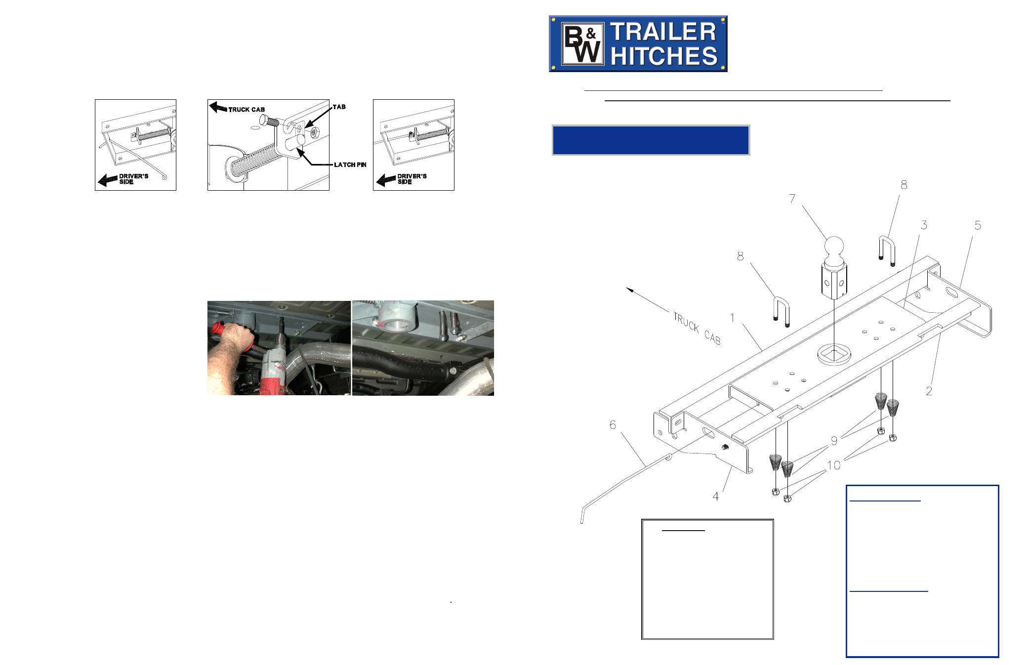
Parts List
1) Front Cross Member
2) Rear Cross Member
3) Center Section
4) Driver’s Side Sideplate
5) Passenger’s Side Sideplate
6) Handle
7) 2-5/16” ball
8) Safety U-Bolts
9) Springs
10) 1/2” Lock nut
Hardware Kit
9 - 1/2”-13 x 1 1/2” cap screws
15 - 1/2”- 13 CR8 Finish Nut
15 - 1/2” Lock Washers
13 - 1/2” Flat Washers
2 - 1/2” -13 x 2” U-Bolts
2 - Side Plate Insert
Safety Chain Kit
2 - 1/2” U-bolts
4 - 1/2” lock nuts
4 - Springs
1 - 3/8”x3/4” Bolt
1 - 3/8” Lock nut
STEP SIX – INSTALL LATCH PIN RELEASE HANDLE
WARNING: LATCH PIN WILL NOT FUNCTION PROPERLY IF HANDLE IS NOT INSTALLED CORRECTLY.
Install the handle from underneath the truck by inserting it through the slot in the end of the center section toward the
driver’s side rear tire as shown. Attach the handle to the latch pin as shown with the handle on the “cab side” of the
square tab welded to the pin. The head of the bolt must be on the handle side, and the lock nut must be on the tab
side. The tab is welded to the pin in an offset position so that the handle will be lined up over the center of the pin. If
the handle is fastened to the other side of the tab, the handle will not function properly. When installed correctly the
latch pin may be disengaged from the ball by pulling on the handle from the driver’s side wheel well and rotating the
handle clockwise.
NOTE: We recommend reading instructions before beginning the installation.
WARNING: The tow vehicle’s towing capacities should under NO circumstances be exceeded.