Install base install leveling kit – B&W Trailer Hitches RVK3600 User Manual
Page 3
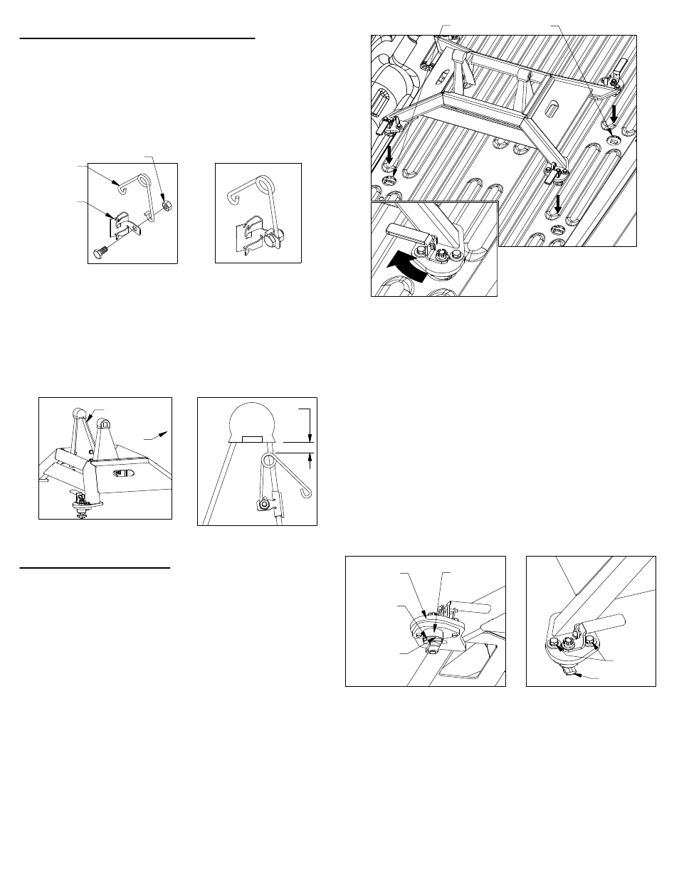
FIGURE C1:
View of unlatched base
INSTALL BASE
INSTALL LEVELING KIT
Locate the 1/4" cap screw and nut, along with the wire
tension spring and mounting clip. Pass the 1/4" cap
screw through the mounting clip and the wire spring
as shown in figure B1. Thread the 1/4" lock nut onto
the 1/4" cap screw. Tighten the lock nut just enough
that the spring will stay in place but will still be able to
rotate around the bolt if needed, see figure B2.
1.
Locate the flange which will be closest to the truck cab
on the driver side pivot arm, see figure B3. The clip
should be placed so that when the springs coil is in the
line with the edge of the arm there will be 1/2" of
clearance between the bottom of the rubber bumper
and the top of the spring, see figure B4. Drive the clip
securely onto the flange with a hammer.
2.
The Companion base will mount to four attachment
points in the truck bed. Remove any debris and/or
obstructions from the truck bed, this includes any
plastic caps which may be over the attachment
points. Remove the latch pins from each of the four
latching mechanisms on the base and rotate the
handles out, see figure C1. Place the Companion
base over the attachment points and carefully lower it
until the pilot keys have passed thought the slots in
each attachment point and the pilot shoulders are
resting flat against the top of the attachment points,
see figure C3.
1.
IMPORTANT: The attachment points may differ from
truck to truck. If the pilots fit into the trucks
attachment points you may skip step 2 and continue
with step 3. If the Companion base does not fit into
the attachment points proceed to step 2.
Each leg of the Companion base has an adjustable
pilot assembly which is attached to the foot with two
1/2" cap screws, as shown in figure C3. To adjust the
pilot assemblies that do not fit into the attachment
points, loosen both the 1/2" cap screws so the pilot
assembly can move freely, see figure C4. Set the
base over the attachment points and adjust the pilot
assemblies until the pilot keys pass through the slot in
the attachment points and the pilot shoulders rest flat
against the top of the attachment points. When all the
pilot assemblies are aligned and inside the
attachment points, push the base towards the cab
and use a tape measure to verify that the base is
approximately square with the truck bed. Tighten any
loose cap screws to 80 ft−lbs.
Once the base is in place, turn each of the latch
handles as shown in figure C2. It is critical that the
base be drawn firmly down onto the attachment points.
You should feel some resistance while turning the
handles as the base is drawn down. If any of the
handles will not close or if they rotate freely, the
tension on the latch handles will need to be adjusted.
Adjustment instructions on next page.
3.
2.
FIGURE C2:
View of closed latch handle
FIGURE B4: Driver
side pivot arm.
FIGURE B1:
Leveling kit parts.
FIGURE B2:
Assembled leveling kit.
FIGURE B3: Base View
FIGURE C4: View of a base foot.
FIGURE C3:
View under base foot
ATTACHMENT POINTS
1/2"
CAB
DRIVER SIDE
PIVOT ARM
MOUNTING
CLIP
WIRE
SPRING
1/4" LOCK NUT
BASE
FOOT
1/2" CAP
SCREW
LATCH CAM
PILOT
KEY
PILOT
ASSEMBLY
PILOT
SHOULDER