B&W Trailer Hitches Turnoverball Model 1059 (Chevrolet_GMC) User Manual
Model 1059r, Turnoverball, Gooseneck hitch installation instructions
www.turnoverball.com
Call or Email us for Installation Support
Turnoverball
TM
Gooseneck Hitch Installation Instructions
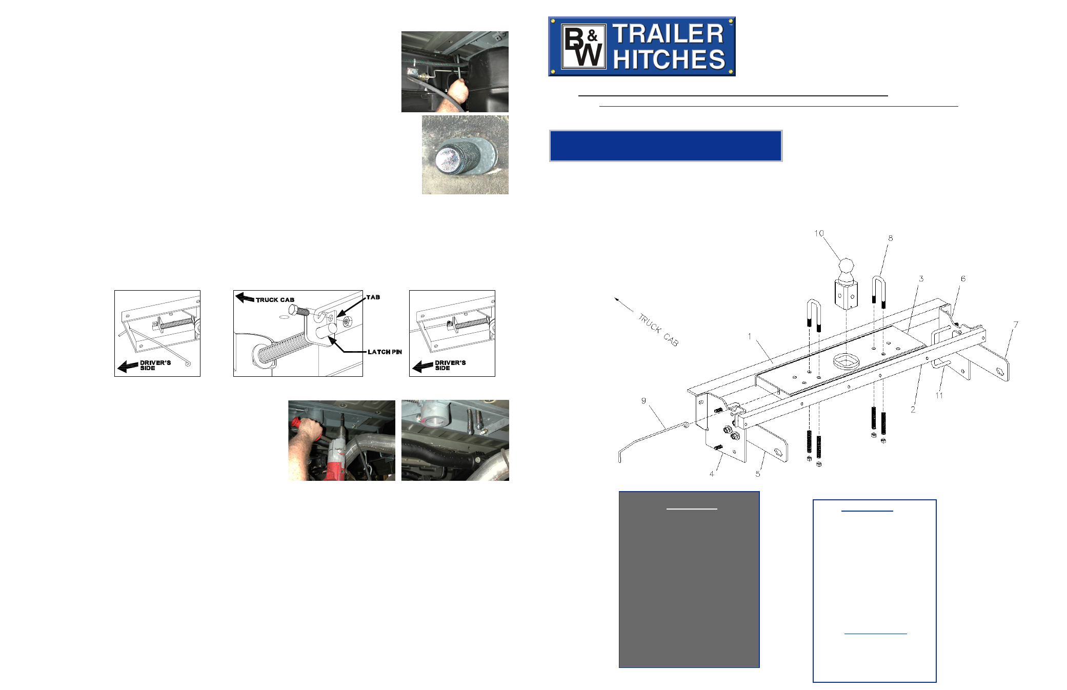
Parts List
1) Front Crossmember
2) Rear Crossmember
3) Center Section
4) Left Front Sideplate
5) Left Rear Sideplate
6) Right Front Sideplate
7) Right Rear Sideplate
8) Safety Chain U-Bolts
9) Latch Pin Handle
10) 2-5/16” Ball
11) 2- 4” x 6 13/64” U-Bolts
12) Springs
13) 1/2” Lock nut
Hardware Kit
Model 1059R
Chevy-GMC (1999-2007)
1/2 & 3/4 Ton, Short & Long Bed (Old Frame & Body Style)
Silverado & Sierra Series
Including Quad-Steer Models
(Includes Heavy Duty 1/2 ton & Light Duty 3/4 ton)
11 - 1/2” x 1 1/2” bolts
2 - 3/4” x 2 1/2” bolts
2 - Side Plate Bushings
2 - 4”x 6 13/64” U-bolts
6 - 1/2” x 1” Carriage Bolts
17 - 1/2” flat washers
4 - 3/4” flat washers
21 - 1/2” lock washers
2 - 3/4” lock washers
15 - 1/2” nuts
2 - 3/4” nuts
1 - O-Ring
Safety Chain Kit
2 - 1/2” U-bolts
4 - 1/2” lock nuts
4 - Springs
1 - 3/8”x3/4” Bolt
1 - 3/8” Lock nut
B&W Trailer Hitches
1216 HWY 224 / PO Box 186
Humboldt, KS 66748
800.248.6564
620.473.3664
Fax:620.473.3766
Copyright 2012
B&W Custom Truck Beds, Inc.
ALL RIGHTS RESERVED
1059R 10 31 2012
STEP TEN - INSTALL SAFETY CHAIN BRACKETS
To install the safety chain brackets (8) it is necessary to drill
four 1/2” holes through the truck bed floor. Drill the holes from
beneath the truck, through the two holes located on each side
and closest to the round receiver tube in the center sec-
tion. This will locate the safety chain brackets (8) in the lowest
point of the floor corrugation. Drop a U-bolt through each pair
of holes from the topside of the truck bed floor. Place a spring
and lock nut on each of the four legs. Tighten the lock nuts
until flush with the bottom of the U-bolts.
STEP ELEVEN - REPLACE THE EXHAUST BRACKET
Replace the exhaust hanger brackets and the spare tire if removed during step 2 of the installation.
STEP EIGHT
Install the ½-inch x 6 ¼-inch U-bolt from inside the frame through the holes in the
sideplate above and below the frame, use a lock washer and nut on each end of the U-
bolt. Repeat this procedure on the passenger side of the truck with the other sideplate.
(While installing the U-bolts around the frame use caution not to damage or pinch the
wiring harness or brake lines). Install the ¾-inch by 2 ½-inch bolt. Place a flat washer
and frame insert on the 3/4” bolt and install the bolt from inside the frame through the
rear hole in the side plate. The 3/4” bolt fastens with a lock washer and nut. (The holes
in the frame and the sideplate are slotted and B&W provides an insert that converts the
slotted holes to a 3/4” round hole. When installed correctly the frame insert will seat firmly in
the slotted hole in the frame and the slotted hole in the sideplate). When completed, tighten
all the hardware in this order: 1. Tighten the center section bolts to the cross members to
80 ft pounds. 2. Make certain the hitch is square with the frame. 3. Tighten the ¾” side plate
bolts to 120 ft pounds. 4. Tighten the frame clamping U-bolts slowly, alternating between
the top and bottom legs of the U-bolt until equally tightened to 40 ft pounds. 5. Tighten the
three carriage bolts on each side to 60 ft pounds. 6. Tighten the side plate to the front and
rear cross members to 80 ft pounds.
STEP NINE – INSTALL LATCH PIN RELEASE HANDLE
WARNING: LATCH PIN WILL NOT FUNCTION PROPERLY IF HANDLE IS NOT INSTALLED CORRECTLY.
Install the handle from underneath the truck by inserting it through the slot in the end of the center section
toward the driver’s side rear tire as shown. Attach the handle to the latch pin as shown with the handle on the
“cab side” of the square tab welded to the pin. The head of the bolt must be on the handle side, and the lock
nut must be on the tab side. The tab is welded to the pin in an offset position so that the handle will be lined
up over the center of the pin. If the handle is fastened to the other side of the tab, the handle will not function
properly. When installed
correctly the latch pin
may be disengaged
from the ball by pulling
on the handle from the
driver’s side wheel well
and rotating the handle
clockwise.
NOTE: We recommend reading instructions before beginning the installation.
WARNING: The tow vehicle’s towing capacities should under NO circumstances be exceeded.