Preparing to install, Install pivot arms – B&W Trailer Hitches RVK3600 User Manual
Page 2
PREPARING TO INSTALL
WARNING: Components of the Companion hitch are
heavy and cumbersome to handle. Failure to use
proper lifting techniques when moving and handling
these parts could result in property damage or
serious injury.
WARNING: B&W also recommends that you check
the clearance between the bed side and the underside
of the front of the trailer and to allow adequate
clearance for the pitch and roll of the trailer while
towing.
WARNING: B&W recommends that you check the
clearance between the truck cab and the trailer.
Compare the measurement taken from the center of
the Coupler to the cab, to the measurement taken
from the center of the king pin to the farthest forward
corner point of the trailer. These measurements will
allow you to see how much clearance you will have
between the cab and the trailer while towing and
turning.
2.
1.
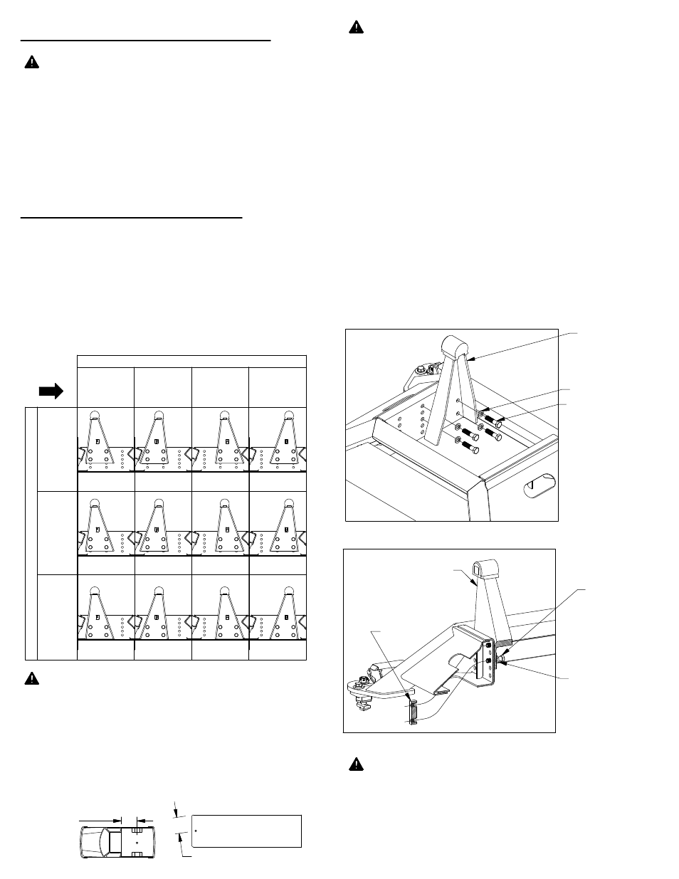
INSTALL PIVOT ARMS
Mount the pivot arms using one of the twelve different
locations illustrated in Table A1. These twelve
locations allow flexibility in coupler height (vertical
adjustment) and distance from the cab (horizontal
adjustment). Choose a location so that your trailer will
be as level as possible and have adequate turning
clearance while towing. See warnings below.
Locate both pivot arms, the four 3/4" threaded blocks,
eight 1/2" cap screws, and eight 1/2" split lock
washers. Place the lock washers over the cap screws.
Align the flat side of the pivot arm flat against the bolt
plate and install four 1/2" cap screws through the
holes on the arm, holding the arm in place, as shown
in figure A2. Locate the threaded blocks. Note that
the sides of the block have threaded holes on one side
and smooth bored holes on the other side. When
installing the threaded blocks it is critical that the side
with the smooth holes is flat against the bolt plate
when installed. Pass the threaded block under the
bases side and align the block with each set of screws
and start each screw, as shown in figure A3. After all
the screws are started through the arms, torque each
bolt to 80 ft−lbs.
Remove all parts from the packaging and familiarize
yourself with all the parts and tools required. Use the
parts list on the front page to verify that all parts and
hardware are present.
WARNING: Installing the thread blocks backwards
will not allow the pivot arms to be fully tightened in the
base and could lead to hitch failure. Before coupling
hitch, be sure that none of the 1/2" x 2" bolts are loose
and the pivot arms are securely attached to the bolt
plate. Failure to check threaded block orientation
could cause serious injury or death.
FIGURE A2: Passenger pivot arm mounting location.
HORIZANTAL ADJUSTMENT
4" BEHIND
AXLE
(FARTHEST
FROM CAB)
2"
BEHIND
AXLE
OVER
AXLE
2" IN FRONT
OF AXLE
(CLOSEST
TO CAB)
V
E
R
T
IC
A
L
A
D
JU
S
T
M
E
N
T
H
IG
H
E
S
T
P
O
S
IT
IO
N
S
(1
9"
)
LO
W
E
S
T
P
O
S
IT
IO
N
S
(1
7"
)
M
E
D
IU
M
H
E
IG
H
T
P
O
S
IT
IO
N
S
(1
8"
)
CAB
DIRECTION
TABLE A1: Pivot arm position table (driver side)
CENTER OF
COUPLER
TO CAB
KING PIN TO EDGE OF TRAILER
PIVOT ARM
1/2" LOCKWASHER
1/2" X 2" CAP SCREW
THREADED
BLOCK
PIVOT ARM
1/2" LOCKWASHER
1/2" X 2"
CAP SCREW