B&W Trailer Hitches Turnoverball Model 1316 (Dodge) User Manual
Model 1316r, Before installing, Turnoverball
B&W Trailer Hitches
1216 HWY 224 / PO Box 186
Humboldt, KS 66748
800.248.6564
620.473.3664
Fax: 620.473.3766
Turnoverball
TM
Gooseneck Hitch Installation Instructions
Call or Email us for Installation Support
Safety Chain Kit
2 - 1/2” U-Bolt
4 - 1/2” Lock Nuts
4 - Springs
1 - 3/8” x 3/4” Hex Cap Screw
1 - 3/8” Lock Nut
1- Brake Line Spacer
Copyright 2011
B&W Custom Truck Beds, Inc.
ALL RIGHTS RESERVED
1316R - 04 19 2011
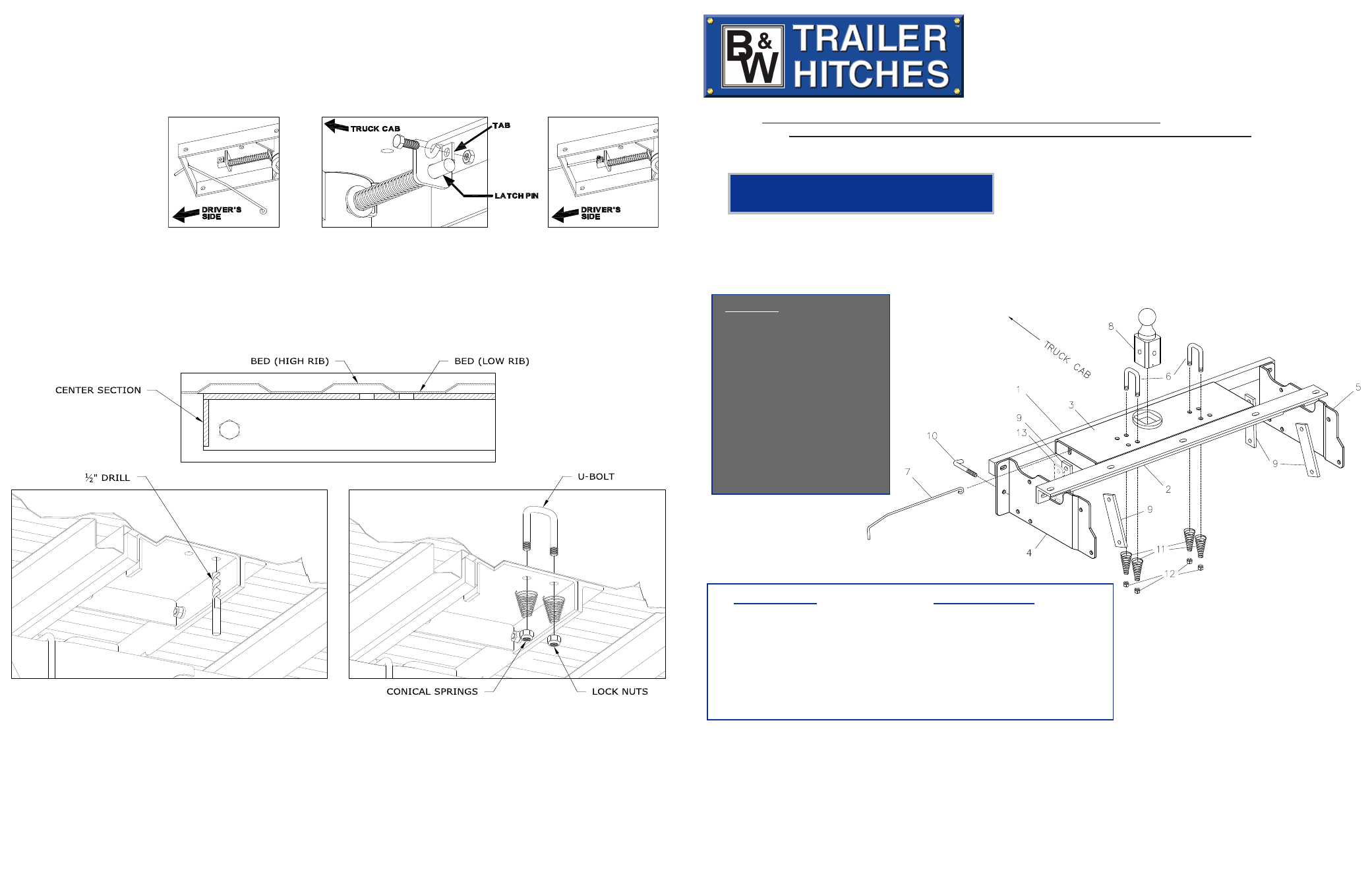
STEP 8
WARNING: LATCH PIN WILL NOT FUNCTION PROPERLY IF HANDLE IS NOT INSTALLED CORRECTLY.
Install the handle from underneath the truck by inserting it through the slot in the end of the center section toward the
driver’s side rear tire as shown. Attach the handle to the latch pin as shown with the handle on the “cab side” of the square
tab welded to the pin. The head of the bolt must be on the handle side, and the lock nut must be on the tab side. The
tab is welded to the pin in an offset position so that the handle will be lined up over the center of the pin. If the handle
is fastened to the other side of the tab, the handle will not function properly. When installed correctly the latch pin may
be disengaged from the ball
by pulling on the handle
from the driver’s side wheel
well and rotating the handle
clockwise.
Model 1316R
Dodge 2002-2008
1/2 Ton, Long & Short Bed
Two and Four-Wheel Drive
Parts List
1 - Front Crossmember
2 - Rear Crossmember
3 - Center Section
4 - Left Sideplate
5 - Right Sideplate
6 - Safety Chain Brackets
7 - Latch Pin Release Handle
8 - 2-5/16” Ball
9 - Clamping Straps
10 - J-Bolt
11 - Tapered Spring
12 - 1/2” Center Lock Nut
13 - Brake Line Spacer
www.turnoverball.com
BEFORE INSTALLING
OVERHEAD LIFTING DEVICE
An overhead-lifting device, such as chain falls, engine hoist, or cable come-a-long, can be used to lift the center sec-
tion of the hitch in place. Lower a loop of rope or chain through the 4” hole in the truck bed floor and attach it to the
latch pin in the round hitch receiver tube in the center section. Use the lifting device to raise the center section until
the round hitch receiver tube that protrudes from the center section fits in the 4” hole in the truck bed floor. Main-
taining upward pressure may facilitate fastening the crossmember to the center section, especially if the truck bed
floor has been distorted downward from heavy use. If you use an overhead-lifting device, it should be disconnected
before squaring the center section across the frame, installing the sideplates and torquing fasteners.
Hardware Kit
11 - 1/2” -13 x 1 1/2” Hex Cap Screw
13 - 1/2” Flat Washers
21 - 1/2” Split Lock Washer
15 - 1/2”-13 Hex Finish Nut
2 - 1/2”-13 x 5” J-Bolt
8 - 1/2”-13 x 4 1/2” Hex Cap Screw
4 - Clamp Straps
STEP 10
Retract the latch pin by pulling the handle out until it stops and then rotating it. Place the 2-5/16” ball in the hitch
receiver. Engage the latch pin by rotating the handle. Be certain the latch pin passes through the holes in the Turn-
overball™ and fully engages through the hitch receiver. Grease the square base of the Turnoverball™.
STEP 9
Install the safety chain U-bolts. The center section may have multiple safety chain holes. Only 4 holes (2 on
each side of the ball) will need to be drilled. Each U-bolt will need to rest in the low part of a bed rib. To deter-
mine which holes will need to be drilled, carefully examine the safety chain holes in the center section to deter-
mine which holes are under a low rib, See figure 9.1. Use a 1/2" Drill bit and drill through the bed in the 4 low rib
locations, See Figure 9.2. Drop a U-bolt through each pair of holes from the top side of the truck bed floor. Place
a conical spring and lock nut on each of the four legs. Tighten the lock nuts until flush with the bottom of the U-
Bolts, See Figure 9.3.
FIGURE 9.1: Cut away view of bed and center section.
FIGURE 9.2: Cut away view from under the bed.
FIGURE 9.3: Cut away view from under the bed.
NOTE: We recommend reading instructions before beginning the installation.
WARNING: The tow vehicle’s towing capacities should under NO circumstances be exceeded.