A anchorspan™ base loads* for temporary structures – Anchor ANCHORSPAN A 60FT-80FT User Manual
Page 34
X-8
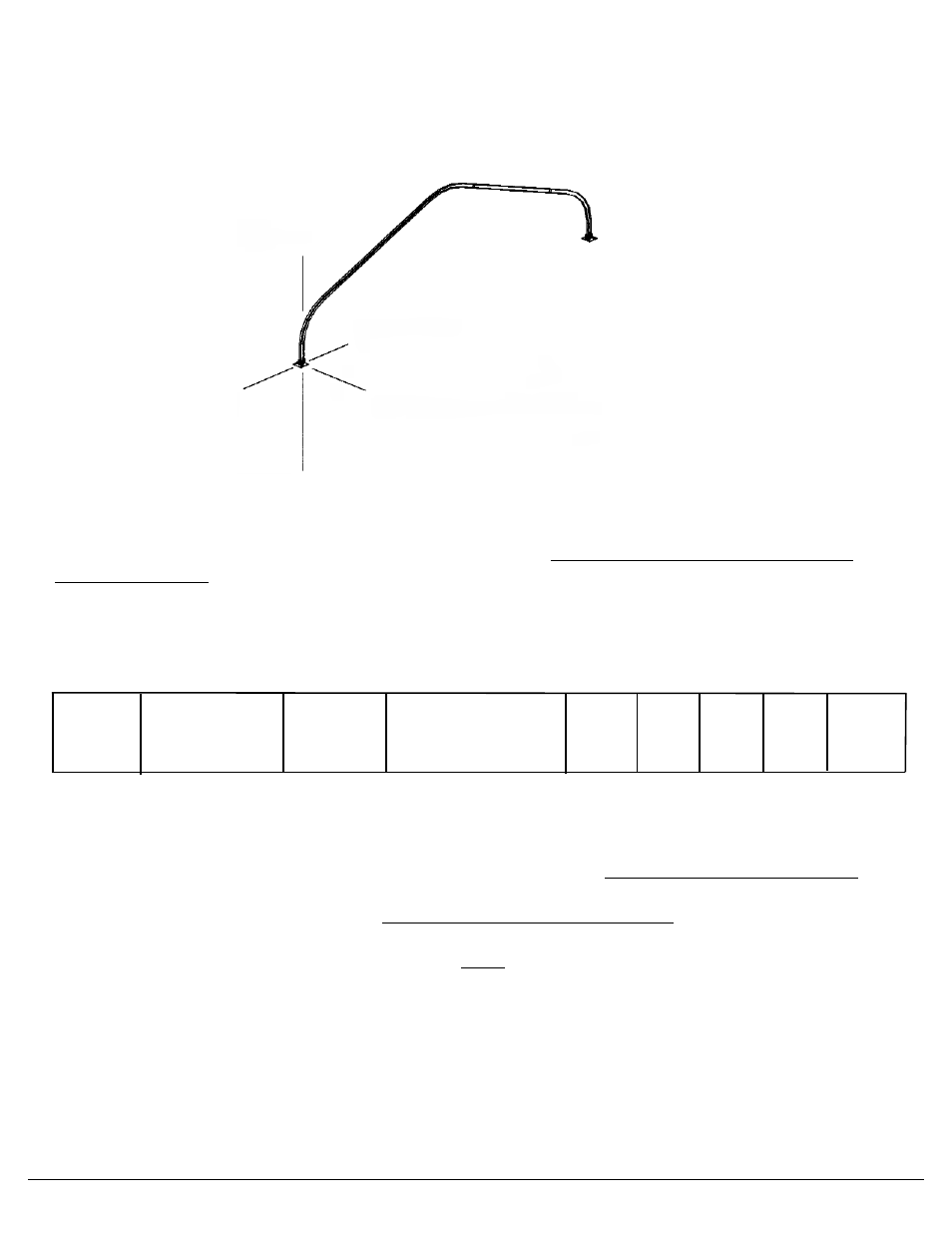
A ANCHORSPAN™
BASE LOADS* FOR TEMPORARY STRUCTURES
70 mph Sustained Wind 90 3 sec Gusts mph gusts ASCE 7-98 Modified for Temporary Use Only
(Revised 6-4-2001)
Also see Introduction, Page 5 “For Permanent Installations”.
* Includes wind loading -- appropriate
stress increases may be used
NOTE: BASELOADS LISTED BELOW ARE IN POUNDS. APPROPRIATE SAFETY FACTORS
MUST BE ADDED: VALUES SHOULD BE CONSIDERED NOMINAL ESTIMATES ONLY. ACTUAL
VALUES WILL BE SUPPLIED ON FOOTPRINT DRAWING.
Span
Term of Use
Bay
Minimum # of
A
B
C
D
E
x-cabled bays*
60’ “A”
Temporary
15’
2 **
2900 1980 2130 1150
1980
70’ “A”
Temporary
15’
2 **
3560 2140 2250 1410
2140
80’ “A” ***
Temporary
15’
2 **
4350 2560 1470** 2000
2560
**NO MORE THAN (5) CONSECUTIVE NON-X-CABLE BAYS ALLOWABLE.
In order for the AnchorSpan to meet the requirements of its engineering calculations and be certifiable
for windspeeds under the ASCE Code modified for temporary use, it must be constructed properly
with the specified minimum number of beams for the given span. It must be properly X-cabled, and
anchoring should be sufficient to withstand vertical and horizontal forces equal to, or greater than,
those shown above on each baseplate plus an appropriate safety factor. Stakes provided with the
unit may not be adequate for the above loads. When appropriate or required, it is the customer’s
responsibility to obtain and install anchoring that does meet the above loads for the soil compaction
and other conditions prevalent at the installation site. See the X-cabling charts on page 3 for proper
cabling.
When properly constructed, each 60’ or 70’ A beam can support 2 lbs per square foot (span times bay
width) of additional dead weight.
***
The 80’ A beam can support a maximum of (3) 333 pound loads distributed symmetrically across the width
of the span (or other approved configurations).
“A”
UPWARD
“E”
INWARD
“B”
OUTWARD
“C”
DOWNWARD
“D”
LATERAL TO FRAME