Anchor ANCHORSPAN A 60FT-80FT User Manual
Page 12
8
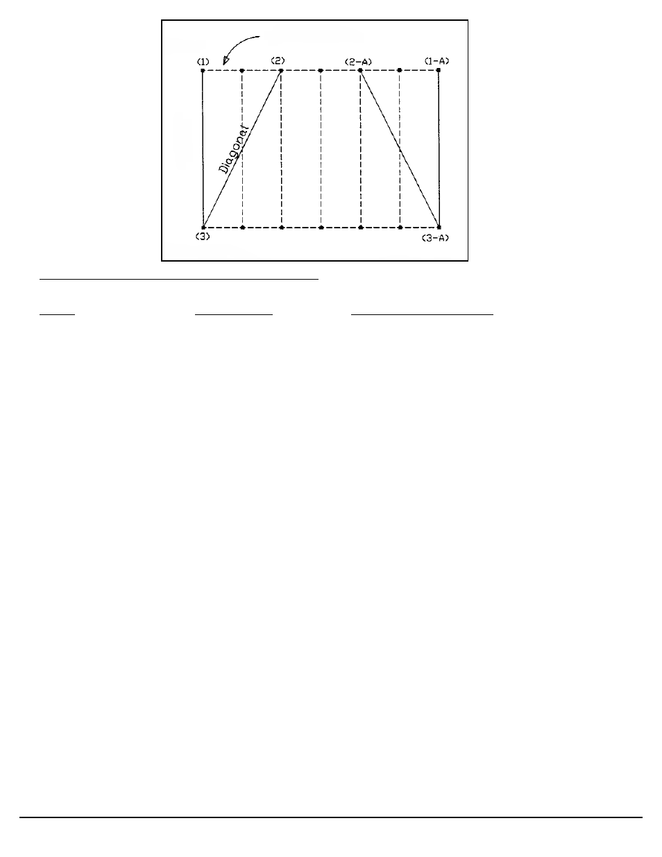
Diagonals to the 3rd Baseplate of Typical Spans
Width
Bay Spacing
Diagonal Measurement
60’
15’ (x2)
67’ 1”
70’
15’ (x2)
76’- 1 7/8”
80’
15’ (x2)
85’- 5 1/4”
Footprint Layout: (Note: For each structure sold, Anchor provides a specific Footprint
Drawing showing plate locations, diagonals and loading requirements for proper anchoring.
* Strike a straight line for “side 1” of the structure according to the desired site orientation.
* Mark 15’ increments along this line and position baseplates (See Footprint Drawing).
* Find an opposite corner by holding the end of one tape at point “1” and another tape at point “2”
and pull straight until the appropriate “width” and “diagonal” measurements for the span you are
installing (see above chart) intersect on the two tapes at point “3”.
* Reverse this procedure to locate the remaining corner on the opposite side of the structure using
points “1-A”, “2-A”, and “3-A”
* Strike a straight line between points “3” and “3-A” representing “side 2”
* Position baseplates in 15’ increments along this side and be sure that opposing baseplates on
opposite sides of the structure are squared toward each other (See Footprint Drawing).
* Drive (4) stakes in each baseplate. Note: depending upon soil conditions and building size, (4)
stakes may not provide the holding power required by engineering analysis for your structure. Where
needed, it is the customer’s responsiblity to provide concrete pier-footings with anchor bolts or appro-
priate earth anchors with holding power greater than the base load reactions shown on the footprint
drawing and engineering calculations for your unit, plus an appropriate safety factor.
BAY SPACING
SIDE ONE
SIDE TWO
Wid
th