Anchor ANCHORSPAN A 60FT-80FT User Manual
Page 23
19
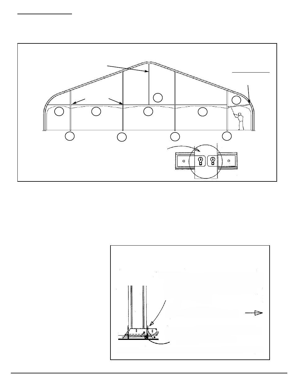
Install End Uprights: (See Bottom of Page 18) One worker stands on base of upright at ground
level, while second worker walks the top of the upright to vertical. Align the T-fitting at the top of
upright with the slot of the upright bracket on the underside of the beam. Lift upright until T-fitting
enters the slot, then rotate the upright 90 degrees with offset to the inside (as shown). (Do not
anchor the uprights until after the eave bars and ground bars have been installed.)
Install end and wing eave bars in the sequence shown above. For later ease of wall installation, be
sure the notch (for inserting wall hooks into the bottom channel of the eave bars) faces toward the
inside of the structure. If this is not done, wall can still be installed, but this alignment will make it
easier.
Consult the Footprint Drawing supplied with your structure for correct positioning and anchor each
upright with (2) 24” stakes (or anchor bolts, depending upon the loading requirements of your instal-
lation). (NOTE: On 40’ and 50’ and 80’ Spans, see Index Page “X-3” for necessary End Center
Bars)
Install Baseplate
Adapter Bars
As Shown. These
are required for
either Gabled Ends
or Sloped Ends.
(If both ends are
installed on the same beam,
only one set of
adapter bars is needed.)
Sequence for Installing End Framing
Install Baseplate Adapter Bars
Note: 40’ & 50’ & 80’ spans use end
center bars at the peak, as shown
At uprights, insert
round rivet head
into keyhole and
drop into slot
WING EAVE BARS
Drop hook end into
Wing Eave Bracket
END EAVE BARS (3)
Keyholed slots
in uprights
VIEW IS FROM OUTSIDE
Drop Slots over baseplate tabs.
Insert bent arm pin into small key-
hole of baseplate.
Insert #10 hair pin cotter to
lock in place.
INSIDE OF STRUCTURE
1
2
3
4
5
6
8
9
7
10