Beam assembly complete – Anchor ANCHORSPAN A 60FT-80FT User Manual
Page 15
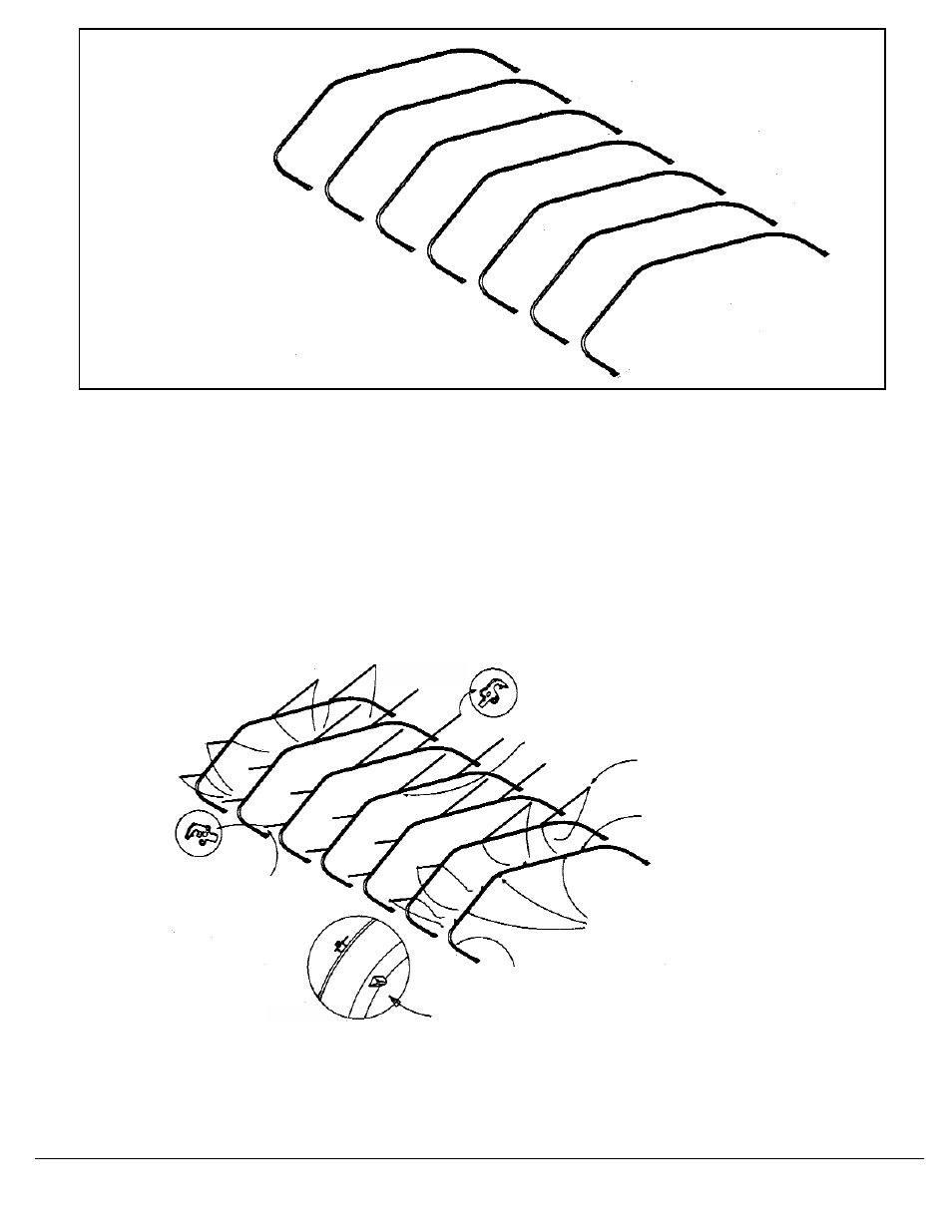
11
Continue assembling beams until all are completed flat on the ground, as above.
Install SpanLatch Purlins and Cross-Cabling:
On all but the first end beam to be raised, bolt the fixed ends of SpanLatch purlins to the top of
the 2” round purlin spacer at each apex joint and each base column joint. For the 80’ span,
see #2, 3, 4, 5, 6, and 7 (in drawing on Page 10). Snug-tighten the locking nut of each purlin
bolt and gently swing each purlin outward & downward until it rests with its stop nut against the
beam (jaws open downward). To avoid damage, do not let purlins swing under their own
momentum. In cross-cabled bays, attach the snap end of each color-coded cable to the
appropriate purlin end and let the turnbuckle end of the cable hang to the ground. (See the
Terminology drawing on Page 3 for the color code of each cable location. See Page 9 for cor-
rect bolt assemblies.)
Before raising first beam, upper ends of cables are snapped to purlins. Upright brackets
and wing eave brackets are installed where needed for Gabled End Frames. (see Hardware
Chart on Page 9)
BEAM ASSEMBLY
COMPLETE
Fixed Ends bolted
to top of 2” Purlin
Spacer
Latching End
Elevated, leaning
against stop, Jaw end
opens downward
Cables attached, turn-
buckles hanging (See
also on last beam for
end bay)
Wing Eave Brackets at
Head of Eave Bolt on
beams with End Frames.
(Viewed on Erect Beam.)
End Beam Bolt Assemblies (Plates
pointing upward) on 1st beam to be
raised.
Upright Bracket Assemblies on any
beams that will have End Framing.
(See page 9)