80’ beam assembly, Beam assembly – Anchor ANCHORSPAN A 60FT-80FT User Manual
Page 14
10
Beam Assembly:
Note: Beams are shipped from the factory with splices pre-installed in base columns and rafters. It
is intended that the horizontal bolts securing the splices be left in place. The ends with the splice are
the male ends, and in all “A” spans the male ends point toward the apex of the structure. Consult
the Hardware Pattern on the previous (facing) page for correct hardware configuration. Bolt
Assembly “O” is used on all overhead joint locations except on the first beam to be raised. Bolt
Assembly “X” is used on overhead joint locations on the end beam that will be raised first and at the
eave purlin locations of cross-cabled bays. These take the place of the fixed end of the SpanLatch™
purlin to secure purlins at locations where they do not overlap.
At the eaves of any beam that will support a gabled end frame, add a wing eave bracket at the
bolt head on the underside of the beam (see locations on hardware chart where the “X” is enclosed
within a square).
Bolt Assembly “B” is used only to hold end uprights (at the non-joint locations) of any beam that
will be equipped with a gabled end frame. At those locations, pop out the hole plug installed at the
factory and insert the Upright Bracket bolt assembly.
The 60’ spans with (2) cross-cabled bays will use (12) “X” Bolt Assemblies, and the 70’ and 80’ spans
will have (14) “X” Bolt Assemblies per structure. All other joint bolt locations will be “O” Bolt
Assemblies. If the structure requires additional X-cabled bays (see X-cable Matrix), (4) additional “X”
Bolt Assemblies will be used per cabled bay.
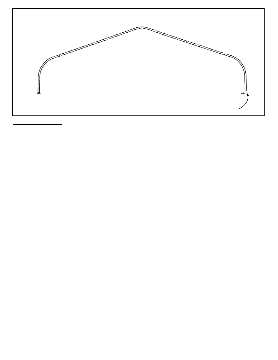
The rafter pattern shown above is for the 80’ span. ( See appendix page X-9 for correct rafter pat-
tern for 40’ to 70’ spans.) Begin assembling the first beam by pinning the female end of one base
column to a baseplate and proceeding toward the opposite side according to the numbered order
shown above. The angled end of the baseplate pin goes to the outside of the structure. In assem-
bling a beam, do not start at both sides and work toward the middle.
The purlin bolt is installed with the head to the underside of the beam and the threads to the top side
of the beam. Be sure the purlin bolt at each joint has been installed before proceeding to the next
joint. At this time, leave the nut loose at the end of the bolt (for later purlin installation). Continue
installing female to male ends at each joint until the opposite side baseplate is reached. Swing the
beam wide of its baseplate (as shown) while the final base column/rafter joint is being assembled.
Then swing the beam back into place and pin the female end of the final base column into it’s base-
plate. Continue assembling beams until all are finished flat on the ground.
Internal splices pre-installed on male ends.
Not visible after installation.
Base
Column
Long Rafter
Short Rafter
Apex
At each joint, male ends point toward the apex.
Swing wide to assemble then
reposition and pin to baseplate
Pin to baseplate, using the “A” bent arm pin
(bent arm to outside)
80’ BEAM ASSEMBLY
1
2
3
4
5
6
7
8