AirLive WL-5470POE User Manual
Page 12
WL-5470 POE User’s Manual
9
1.3 Installing WL-5470POE
This section describes the installation procedure for the WL-5470POE. It starts with a summary of the content
of the package you have purchased, followed by steps of how to power up and connect the WL-5470POE.
Finally, this section explains how to configure a Windows PC to communicate with the WL-5470POE.
1.3.1 Package Content
The WL-5470POE package contains the following items:
9
One WL-5470POE main unit
9
One 12V DC power adapter
9
Indoor detachable Omni Antenna x 1
9
One CD of the WL-5470POE
9
Quick Start Guide
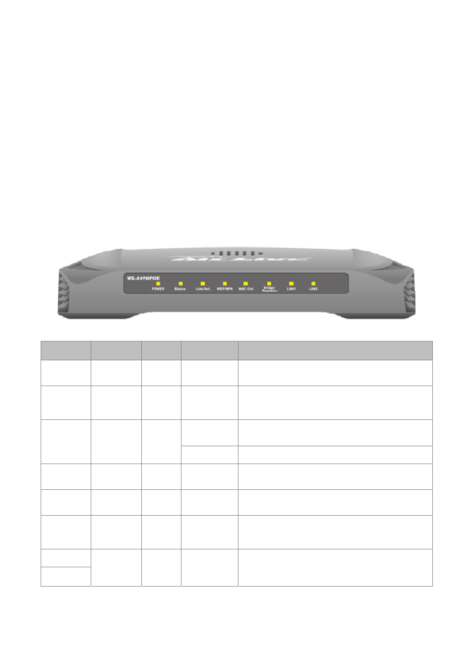
1.3.2 Hardware Presentation
LED #
Function
Color
Status
Description
Power Power
indication
Green
Solid
Power is being applied to this product.
Status Firmware
executions
indicator
Green
On and Off
Turns solid green when the device is booting, after
boot successfully, the light turn off.
Solid
Turns solid green when connected and associated to
at least a client station.
Link/Act LAN
port
activity
Green
Blinking Receiving/Sending
data
WEP/WPA Encryption
Status
Green
Solid
Turns solid orange when wireless security is
enabled.
MAC Ctrl
MAC Ctril
Status
Green
Solid
Turns solid light when MAC Control is enabled.
Bridge /
Repeater
Bridge
Repeater
indicator
Green
Solid
Turn solid light when Bridge or Repeater is enabled.
LAN 1
LAN 2
Link activity Green
Blinking
An active station is connected to the corresponding
LAN port.
Table 1: LED Indicators